
User Manual Owner's manual

Rockwell Automation Publication 2711P-UM006C-EN-P - April 2013 125
Install and Replace Components Chapter 5
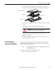
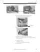
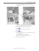
4. Disconnect the touch screen connector.
5. Remove the screws from the back of the display module.
The number of screws varies for each terminal type.
6. Remove the sealing gasket.
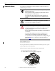
7. Lift the back of the display module away from the bezel.
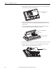
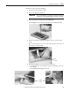
Work on a clean, flat, stable surface to protect the display from debris,
scratches and damage.
8. Detach the connectors.
• Function key connector
• Connector on keypad or keypad/touch units
9. Set the bezel aside.
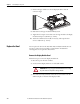
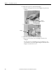
Plate
Touch Screen Connector
Display Module Bezel