Installation Instructions Mounting Levers for PanelView Plus 400 and 600 Terminals Catalog Number 2711P-RTFC Inside... English...................................................3 Français.................................................5 Deutsch .................................................7 Español..................................................9 Italiano ................................................11 Português ............................................
Mounting Levers Important User Information Because of the variety of uses for the products described in this publication, those responsible for the application and use of these products must satisfy themselves that all necessary steps have been taken to assure that each application and use meets all performance and safety requirements, including any applicable laws, regulations, codes and standards.
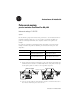
Installation Instructions Mounting Levers for PanelView Plus 400 and 600 Terminals Catalog Number 2711P-RTFC English This document provides instructions on how to install the PanelView Plus 400 and 600 Terminals in a panel or enclosure using the 2711P-RTFC mounting levers. Eight mounting levers are provided with kit. The mounting levers hold the terminal tightly against the mounting enclosure. The number of levers used for installation varies for each device.
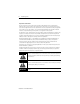
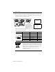
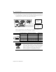
Mounting Levers 3. Rotate each lever in the direction indicated until lever is in final latch position. Follow the latching sequence below to obtain optimum terminal fit. 1 4 4 Levers Notch 6 3 1 Alignment Marks Rotate until notch in levers align with proper alignment mark on terminal. 1 2 5 3 6 Levers 4 2 6 Use the table below as a guide to insure an adequate gasket seal between terminal and panel.
Notice d'installation Attaches de fixation pour terminaux PanelView Plus 400 et 600 Référence 2711P-RTFC Français Le présent document indique comment installer les terminaux PanelView Plus 400 et 600 sur un panneau ou dans une armoire à l’aide des attaches de fixation 2711P-RTFC. Le kit contient huit attaches de fixation. Les attaches de fixation maintiennent fermement le terminal contre le support de montage. Le nombre d’attaches utilisées pour l’installation varie d’un terminal à l'autre.
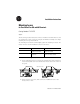
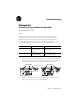
Attaches de fixation 3. Faites-les ensuite pivoter dans la direction indiquée jusqu'à ce qu’elles soient verrouillées. Suivez la séquence de verrouillage ci-dessous afin que votre terminal soit maintenu le mieux possible. 1 4 4 attaches Encoche 6 1 3 Repères d’alignement Faites pivoter l’attache jusqu’à ce que la petite encoche située sur l’attache soit en face du repère d’alignement qui convient sur le terminal.
Installationsanleitung Montagehebel für Terminals des Typs PanelView Plus 400 und 600 Bestellnummer 2711P-RTFC Deutsch Das vorliegende Dokument enthält eine Anleitung zur Montage der Terminals PanelView Plus 400 und 600 in einem Schaltschrank oder Gehäuse mithilfe der Montagehebel 2711P-RTFC. Acht Montagehebel sind im Lieferumfang enthalten. Die Montagehebel drücken das Terminal eng gegen die Montageplatte. Die Anzahl der für die Installation benötigten Hebel ist je nach Gerät unterschiedlich.
Montagehebel 3. Drehen Sie jeden Hebel so lange in die angegebene Richtung, bis er sich in der endgültigen Verriegelungsposition befindet. Folgen Sie der nachfolgend dargestellten Verriegelungsreihenfolge, um einen optimalen Sitz des Terminals zu erhalten. 1 4 4 Hebel Kerbe 6 3 1 Ausrichtungsmarkierung Drehen Sie so lange, bis die Hebelkerbe der richtigen Ausrichtungsmarkierung des Terminals gegenüberliegt.
Instrucciones de instalación Palancas de montaje para los terminales PanelView Plus 400 y 600 Número de catálogo 2711P-RTFC Español Este documento proporciona instrucciones para llevar a cabo la instalación de los terminales PanelView Plus 400 y 600 en un panel o envolvente mediante las palancas de montaje 2711P-RTFC. Este conjunto contiene ocho palancas de montaje. Las palancas de montaje sostienen firmemente al terminal en el envolvente de montaje.
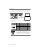
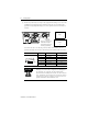
Palancas de montaje 3. Gire cada palanca en la dirección indicada hasta que llegue a la posición de enclavamiento final. Continúe con la secuencia de enclavamiento indicada a continuación para obtener un ajuste del terminal óptimo. 1 4 4 palancas Muesca 6 3 1 Marcas de alineación Gire hasta que la muesca de las palancas esté alineada con la marca de alineación del terminal.
Istruzioni per l'installazione Levette di montaggio per terminali PanelView Plus 400 e 600 Numero di catalogo 2711P-RTFC Italiano Questo documento descrive come installare i terminali PanelView Plus 400 e 600 su un pannello o in una custodia utilizzando le levette di montaggio 2711P-RTFC. Il kit contiene otto levette di montaggio. Le levette servono per bloccare il terminale alla custodia di montaggio. Il numero di levette utilizzate varia in base al tipo di dispositivo.
Levette di montaggio 3. Ruotare le levette nella direzione indicata fino a portarle nella posizione finale di blocco. Attenersi alla sequenza di chiusura indicata sotto per ottenere un blocco ottimale del terminale. 1 4 4 Levette Tacca 6 3 1 Segni di allineamento 1 Ruotare fino a quando la tacca delle levette risulta in linea con il segno di allineamento 4 del terminale. 2 5 3 6 Levette 2 6 Usare la tabella sottostante come guida per garantire un'adeguata tenuta tra terminale e pannello.
Instruções de Instalação Alavancas de Fixação para Terminais PanelView Plus 400 e 600 Código de Catálogo 2711P-RTFC Português Este documento fornece instruções para a instalação dos terminais PanelView Plus 400 e 600 em um painel ou gabinete usando as alavancas de fixação 2711P-RTFC. Oito alavancas de fixação são fornecidas com o kit. As alavancas de fixação prendem o terminal firmemente no gabinete de fixação. O número de alavancas usadas para instalação varia para cada dispositivo.
Alavancas de Fixação 3. Gire cada alavanca no sentido indicado até chegar à posição final de travamento. Siga a seqüência de travamento abaixo para obter o encaixe perfeito do terminal. 1 4 4 Alavancas Entalhe 6 3 1 Marcas de Alinhamento Gire até que o entalhe das alavancas esteja alinhado com a marca de alinhamento correta do terminal. 2 1 5 3 6 Alavancas 4 2 6 Use a tabela abaixo como guia para garantir a vedação adequada da junção entre o terminal e o painel.
Publication 2711P-IN016A-MU-P
Publication 2711P-IN016A-MU-P - August 2003 PN 41061-321-01(1) Copyright © 2003 Rockwell Automation, Inc. All rights reserved. Printed in the U.S.A.