Installation Instructions High-bright Display Modules Catalog Number 2711P-RDT12H Topic Page Important User Information 2 Environment and Enclosure 3 Outdoor Installation 4 Hazardous Locations 5 Environnements dangereux 6 Wiring and Safety Guidelines 9 About the Terminals 10 Install the Terminal 11 Logic Module Compatibility 15 External Power Supply For Nonisolated DC Terminals 16 External Power for Isolated DC Terminals 16 Remove and Install the Power Terminal Block 18 DC Power
High-bright Display Modules Important User Information Solid state equipment has operational characteristics differing from those of electromechanical equipment. Safety Guidelines for the Application, Installation and Maintenance of Solid State Controls (Publication SGI-1.1 available from your local Rockwell Automation sales office or online at http://literature.rockwellautomation.com) describes some important differences between solid state equipment and hard-wired electromechanical devices.
High-bright Display Modules 3 Environment and Enclosure See the Outdoor Installation section for additional enclosure and certification information on the high-bright display modules. ATTENTION This equipment is intended for use in a Pollution Degree 2 industrial environment, in overvoltage Category II applications (as defined in IEC publication 60664-1), at altitudes up to 2000 m (6561 ft) without derating.
High-bright Display Modules Outdoor Installation When using the high-bright display module, catalog number 2711P-RDT12H, outdoors, considerations in maximizing the field life of the front bezel and display are: • selecting the proper enclosure. • orientation of the terminal. Both ultraviolet and infrared radiation can reduce the field life of any electronic device. While the materials used in the terminal bezels provide long field life, that life can be improved by proper installation.
High-bright Display Modules 5 Hazardous Locations This equipment is suitable for these locations: • • • • • Class I, Division 2 Groups A, B, C, D Class I, Zone 2, Group IIC Class II, Division 2 Groups F, G Class III Ordinary, nonhazardous locations only The following statement applies to use in hazardous locations. WARNING Explosion Hazard • Substitution of components may impair suitability for hazardous locations.
High-bright Display Modules Environnements dangereux Cet équipement ne peut être utilisé que dans les environnements suivants : • • • • Classe I, Division 2, Groupes A, B, C, D Classe II, Division 2, Groupes F, G Classe III ou environnements non-dangereux La mise en garde suivante s’applique à une utilisation en environnement dangereux. AVERTISSEMENT DANGER D’EXPLOSION • La substitution de composants peut rendre cet équipement impropre à une utilisation en environnement dangereux.
High-bright Display Modules 7 USB Ports The terminals contain universal serial bus (USB) ports that comply with hazardous location environments. This section details the field-wiring compliance requirements and is provided in accordance with the National Electrical Code, article 500.
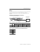
High-bright Display Modules Application Information Per the National Electrical Code the circuit parameters of nonincendive field wiring apparatus for use in hazardous locations shall be coordinated with the associated nonincendive field wiring apparatus such that their combination remains nonincendive. The PanelView Plus 700 to 1500 and the USB peripheral device shall be treated in this manner. The circuit parameters of the PanelView Plus 700 to 1500 USB port are given in Table 1.
High-bright Display Modules 9 Wiring and Safety Guidelines Use publication NFPA 70E, Electrical Safety Requirements for Employee Workplaces, IEC 60364 Electrical Installations in Buildings, or other applicable wiring safety requirements for the country of installation when wiring the devices. In addition to the NFPA guidelines: • connect the device and other similar electronic equipment to its own branch circuit. • protect the input power by a fuse or circuit breaker rated at no more than 15 A.
High-bright Display Modules About the Terminals The PanelView Plus terminals have these modular components: • 1250 high-bright touch display module • Logic module with DC power, CompactFlash card slot, Ethernet port, serial port, USB ports • Internal CompactFlash card with firmware or operating system, RAM memory (SO-DIMM) • Communication module for specific communication protocols High-bright display modules are available only as separate components.
High-bright Display Modules 11 Required Tools These tools are required for installation: • Panel cutout tools • Small, slotted screwdriver • Torque wrench (lb•in) Install the Terminal Before installing the terminal in a panel, review these topics: • Mounting clearances • Panel cutout dimensions • Product dimensions Mounting Clearances Allow adequate clearance around the terminal, inside the enclosure, for adequate ventilation. Consider heat produced by other devices in the enclosure.
High-bright Display Modules Mount the Terminal in a Panel Four mounting clips secure the terminal to the panel. ATTENTION Disconnect all electrical power from the panel before making the panel cutout. Make sure the area around the panel cutout is clear. Take precautions so metal cuttings do not enter any components already installed in the panel. Failure to follow these instructions may result in personal injury or damage to panel components. Follow these steps to mount the terminal in a panel. 1.
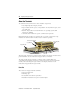
High-bright Display Modules 13 4. Slide the ends of the mounting clips into the slots on the terminal. Mounting Clip Mounting Clip Slot 5. Tighten the mounting clip screws by hand until the gasket seal contacts the mounting surface uniformly. 6. Tighten the mounting clip screws to a torque of 0.90…1.1 N•m (8…10 lb•in) by using the specified torque sequence, making sure not to over-tighten.
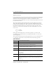
High-bright Display Modules Product Dimensions The illustration shows product dimensions for the PanelView Plus or PanelView Plus CE 1250 touch screen terminals with the high-bright display module. Depth dimensions are shown for: • base configured unit (display module and logic module). • base configured unit with communication module. Measurements are in mm (in). 1250 High-bright Touch Screen 363 (14.30) a 74 (2.90) Display to Logic Module b 101 (3.
High-bright Display Modules 15 Logic Module Compatibility The high-bright display module is only compatible with the following DC logic modules. PanelView Plus and PanelView Plus CE Logic Modules Cat. No.
High-bright Display Modules External Power Supply For Nonisolated DC Terminals TIP To identify nonisolated DC logic modules refer to the PanelView Plus Terminals User Manual, publication 2711P-UM001. Use a single, 24V DC power supply, such as catalog number 2711P-RSACDIN, to power each PanelView Plus device. Using a separate, isolated and ungrounded source to power each terminal prevents ground loop currents from damaging the terminals.
High-bright Display Modules 17 Earth/Ground Connection PanelView Plus devices with a DC power input have an earth/ground terminal that you must connect to a low-impedance earth/ground. The earth/ground connection is on the rear of the display module. IMPORTANT The earth/ground connection to ground is mandatory. This connection is required for noise immunity, reliability, and Electromagnetic Compliance (EMC) with the European Union (EU) EMC directive for CE-mark conformance.
High-bright Display Modules Remove and Install the Power Terminal Block The terminals ship with a power terminal block installed. You can remove and reinstall the terminal block for ease of installation, wiring, and maintenance. WARNING Explosion Hazard • Substitution of components may impair suitability for hazardous locations. • Do not disconnect equipment unless power has been switched off and area is known to be nonhazardous.
High-bright Display Modules 19 DC Power Connections DC-powered PanelView Plus devices have an integrated 24V DC power supply. Both isolated and nonisolated power supplies have these ratings: • 24V DC nominal (18…32V DC) • 70 W maximum (2.9 A at 24V DC) The power supply is internally protected against reverse polarity of the DC+ and DC- connections. The input power terminal block supports these wire sizes.
High-bright Display Modules Connect DC Power WARNING Explosion Hazard - Do not disconnect equipment unless power has been switched off and the area is known to be nonhazardous. Disconnect all power before installing or replacing components. Failure to disconnect power may result in electrical shock or damage to the terminal. Follow these steps to connect the terminal DC power. 1. Verify that the terminal is not connected to a power source. 2. Secure the DC power wires to the terminal block.
High-bright Display Modules 21 Ethernet Cable For PanelView Plus 700 to 1500 terminals, use Belden 7921A shielded Ethernet Category 5e cable according to TIA 568-B.1 and RJ45 connector according to IEC 60603-7 for compliance with the European Union 89/336/EEC EMC Directive. The maximum cable length between the terminal’s Ethernet port and a 10/100 Base-T port on an Ethernet hub (without repeaters or fiber) is 100 m (328 ft).
High-bright Display Modules After a successful startup, both indicators are off and controlled by the application running on the terminal. The table shows indicator states if the terminal powers up and stops during startup. Indicator States if the Terminal Stops During Startup Fault (Red) Indicator Comm (Green) Indicator Description Recommended Action Blinking red indicator identifies a recoverable error. Blinking Off Last firmware download failed.
High-bright Display Modules 23 Start-up Information Messages Start-up information messages display in a specific sequence on the terminal during startup and typically display for a few seconds. These messages do not require that you perform any action. Message # Message Description 37 Video Initialized Configures and initializes the graphics video system. 30 Watchdog Test Tests the watchdog circuitry to verify system integrity. 1 RAM Test Tests the RAM memory.
High-bright Display Modules Start-up Error Messages When an error occurs, the terminal displays an error number with a text message. The word ERROR! appears under the message in different languages. # Displayed Message ERROR! FEHLER! ERREUR! ERRORE! Error # Message Description Recommended Corrective Action 1 RAM Test RAM test failure. Reset the terminal. If error persists, reseat the SO-DIMM RAM module. If error still persists, replace the logic module.
High-bright Display Modules 25 Specifications PanelView Plus or PanelView Plus CE Terminal with High-bright Display Module - 2711P-RDT12H Attribute Value Display Display type Color active matrix, thin film transistor (TFT) liquid crystal display (LCD) Display size 12.1 in. Display area (W x H) 246 x 184 mm (9.7 x 7.2 in.
High-bright Display Modules Environmental Specifications Specification Value Temperature, operating 0…55 °C (32…131 °F) Temperature, nonoperating -20…70 °C (-13…158 °F) Vibration 10… 57 Hz, 0.012 pk-pk displacement 57…500 Hz 2.
High-bright Display Modules 27 Additional Resources For additional information on the PanelView Plus and PanelView Plus CE terminals, refer to these publications. Resource Description PanelView Plus Terminal User Manual, publication 2711P-UM001 Provides an overview of the PanelView Plus and PanelView Plus CE terminals and gives information on how to install, operate, configure, and troubleshoot these devices.
Rockwell Automation Support Rockwell Automation provides technical information on the Web to assist you in using its products. At http://support.rockwellautomation.com, you can find technical manuals, a knowledge base of FAQs, technical and application notes, sample code and links to software service packs, and a MySupport feature that you can customize to make the best use of these tools.