
Manual


Cutout Adapter Kit 7
Publication 2711P-IN021A-MU-P
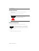
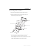
4. Rotate each lever in the direction indicated until lever is in final latch position. Follow
the latching sequence below to obtain optimum terminal fit.
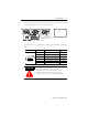
Use the table below as a guide to insure an adequate gasket seal between terminal and
panel.
Lever Position Panel Thickness Range Typical Gauge
1 0.15 - 2.01 mm (0.060 - 0.079 in) 16
2 2.03 - 2.64 mm (0.08 - 0.104 in) 14
3 2.67 - 3.15 mm (0.105 - 0.124 in) 12
4 3.17 - 3.66 mm (0.125 - 0.144 in) 10
5 3.68 - 4.16 mm (0.145 - 0.164 in) 8/9
6 4.19 - 4.75 mm (0.165 - 0.187 in) 7
ATTENTION
!
Follow instructions above to provide a proper seal and
to prevent potential damage to the terminal.
Allen-Bradley assumes no responsibility for water or
chemical damage to the terminal or other equipment
within the enclosure because of improper installation.
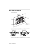
6 Levers
246
513
1
6
Notch
Alignment Marks
Rotate until notch in levers align
with proper alignment mark on
terminal.
1
2
3
4
5
6
Terminal Markings
for Alignment