
Reference Manual

133Scrolling Lists
Publication 2711E-820 – January 1998
The following table displays the addresses for each of the additional
buttons:
Additional Buttons Command BLK
Transfer Address
Indicator State
BLK Transfer
Address
PLC Address
AUTO MODE
BI52/1 (Value = 1) N30:3/1 (Value = 1)
MANUAL MODE BI52/1 (Value = 0) N30:3/1 (Value = 0)
TOGGLE
COMMAND
BI52/3 N30:3/3
BI52/1 N30:3/1
SET COMMAND
BI52/0 N30:3/0
BI52/1 N30:3/1
MANUAL ON
BI52/4 N30:3/4
BI52/1 N30:3/1
MANUAL OFF
BI52/5 N30:3/5
BI52/1 N30:3/1
NUMERIC KEYPAD
ENTER KEY FOR
STYLE NUMBER
BI52/6 N30:3/6
CHANGE STYLE
NO. CONTROL
ADDR
BI53/0 — 3/15 N30:4
The following table displays the addresses for the Object List PLC
files:
Object List PLC Files PLC File Addresses PLC File Data Presets
ASSEMBLY STATION
N31:1 through N31:57 1 through 57
LUXURY OPTION N32:1 through N32:57 1 through 57
STATION STATUS N33:1 through N33:57 1
OPTION COMMAND N34:1 through N34:57 1
OPTION STYLE NO. N35:1 through N35:57 100
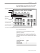
When you have assigned all the addresses for the Object List PLC
files, you are ready to begin programming the PLC.
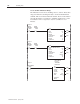
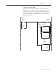
Step 3: Program the PLC
To program the PLC, follow the ladder diagrams shown in the
following pages.