
Quick Start User Manual
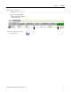


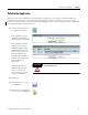
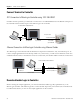
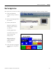
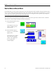
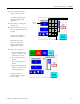
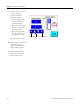
Table Of Contents
- 2711C-QS001F-EN-P PanelView Component HMI Quick Start
- Where to Start
- Preface
- Chapter 1
- Chapter 2
- Chapter 3
- Chapter 4
- Chapter 5
- Chapter 6
- Create the Motor Status Screen
- Introduction
- Before You Begin
- What You Need
- Follow These Steps
- Change the Screen Name
- Change the Grid Attributes
- Create the Start Motor Push Button
- Create the Stop Motor Push Button
- Create the Motor Speed Screen Button
- Create a Goto Config Button
- Create the Motor Control List Selector
- Create the Motor Status Indicators
- Save the Motor Status Screen
- Create the Motor Status Screen
- Chapter 7
- Create the Motor Speed Screen
- Introduction
- Before You Begin
- What You Need
- Follow These Steps
- Create a New Screen
- Create the Motor Status Screen Button
- Create a Numeric Entry Object
- Create a Heading for the Numeric Entry Object
- Create a Increment Decrement Object
- Create Increment Decrement Keys
- Create a Bar Graph
- Create a Bar Graph Scale
- Create Text Labels for the Scale
- Create a Bar Graph Heading
- Create a Numeric Display
- Create a Heading for the Numeric Display
- Update the Motor Speed Screen Button
- Create the Motor Speed Screen
- Chapter 8
- Chapter 9
- Appendix A
- Back Cover
96 Publication 2711C-QS001F-EN-P - November 2010
Chapter 9 Validate and Run Application
Connect Terminal to Controller
DF1 Connection to MicroLogix Controller using 1761-CBL-PM02
For DF1 runtime operation, you will need to connect the 1761-CBL-PM02 between the RS-232 serial port of
the terminal and the Channel 0 port of the MicroLogix 1100 controller.
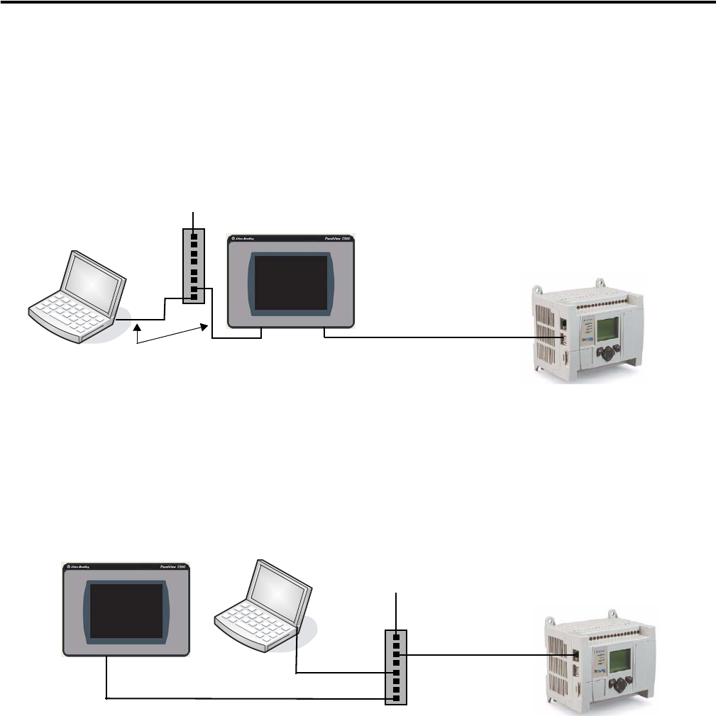
Ethernet Connection to MicroLogix Controller using Ethernet Cables
The MicroLogix 1100 controller and the PanelView Component terminal have only one Ethernet port. To
run the sample application from the Startup window of your browser, you will need an Ethernet switch. Use
standard Ethernet cables or the Ethernet crossover CAT5 cable, 2711P-CBL-EX04 to make the connections.
Download Ladder Logic to Controller
Before running the sample application, you must download the ladder logic file, QuickStart.rss, to the
MicroLogix controller. This ladder logic file is on the CD that ships with your terminal. The controller must
be in Run mode before you can run the sample application on the terminal.
Ethernet Cable
Ethernet Port
10/100Base-T
Channel 0 Port
RS-232/485
8-pin Mini DIN
1761-CBL-PM02 Cable
RS-232 Serial Port
9-pin D-shell
To Ethernet DHCP-enabled Network
DF1 Connection
Ethernet Cable
Ethernet Port
10/100Base-T
Channel 1 Port
Ethernet 10/100Base-T
Ethernet Cable
Ethernet Cable
To Ethernet DHCP-enabled Network