
Quick Start User Manual


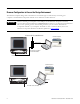
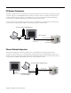

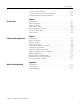

Table Of Contents
- 2711C-QS001F-EN-P PanelView Component HMI Quick Start
- Where to Start
- Preface
- Chapter 1
- Chapter 2
- Chapter 3
- Chapter 4
- Chapter 5
- Chapter 6
- Create the Motor Status Screen
- Introduction
- Before You Begin
- What You Need
- Follow These Steps
- Change the Screen Name
- Change the Grid Attributes
- Create the Start Motor Push Button
- Create the Stop Motor Push Button
- Create the Motor Speed Screen Button
- Create a Goto Config Button
- Create the Motor Control List Selector
- Create the Motor Status Indicators
- Save the Motor Status Screen
- Create the Motor Status Screen
- Chapter 7
- Create the Motor Speed Screen
- Introduction
- Before You Begin
- What You Need
- Follow These Steps
- Create a New Screen
- Create the Motor Status Screen Button
- Create a Numeric Entry Object
- Create a Heading for the Numeric Entry Object
- Create a Increment Decrement Object
- Create Increment Decrement Keys
- Create a Bar Graph
- Create a Bar Graph Scale
- Create Text Labels for the Scale
- Create a Bar Graph Heading
- Create a Numeric Display
- Create a Heading for the Numeric Display
- Update the Motor Speed Screen Button
- Create the Motor Speed Screen
- Chapter 8
- Chapter 9
- Appendix A
- Back Cover
Publication 2711C-QS001F-EN-P - November 2010 5
DF1 Runtime Configuration
The DF1 configuration shows the PanelView Component C600 terminal connected to the MicroLogix 1100
controller using the 1761-CBL-PM02 cable. One end of the cable connects to the RS-232 serial port of the
terminal and the other end connects to the Channel 0 port of the controller. The terminal and computer
are connected to a DHCP-enabled Ethernet network using an Ethernet switch.
You can substitute another MicroLogix model in place of the MicroLogix 1100 controller. For MicroLogix
controllers with a 9-pin D-shell connector, use the catalog number 1747-CP3 cable.
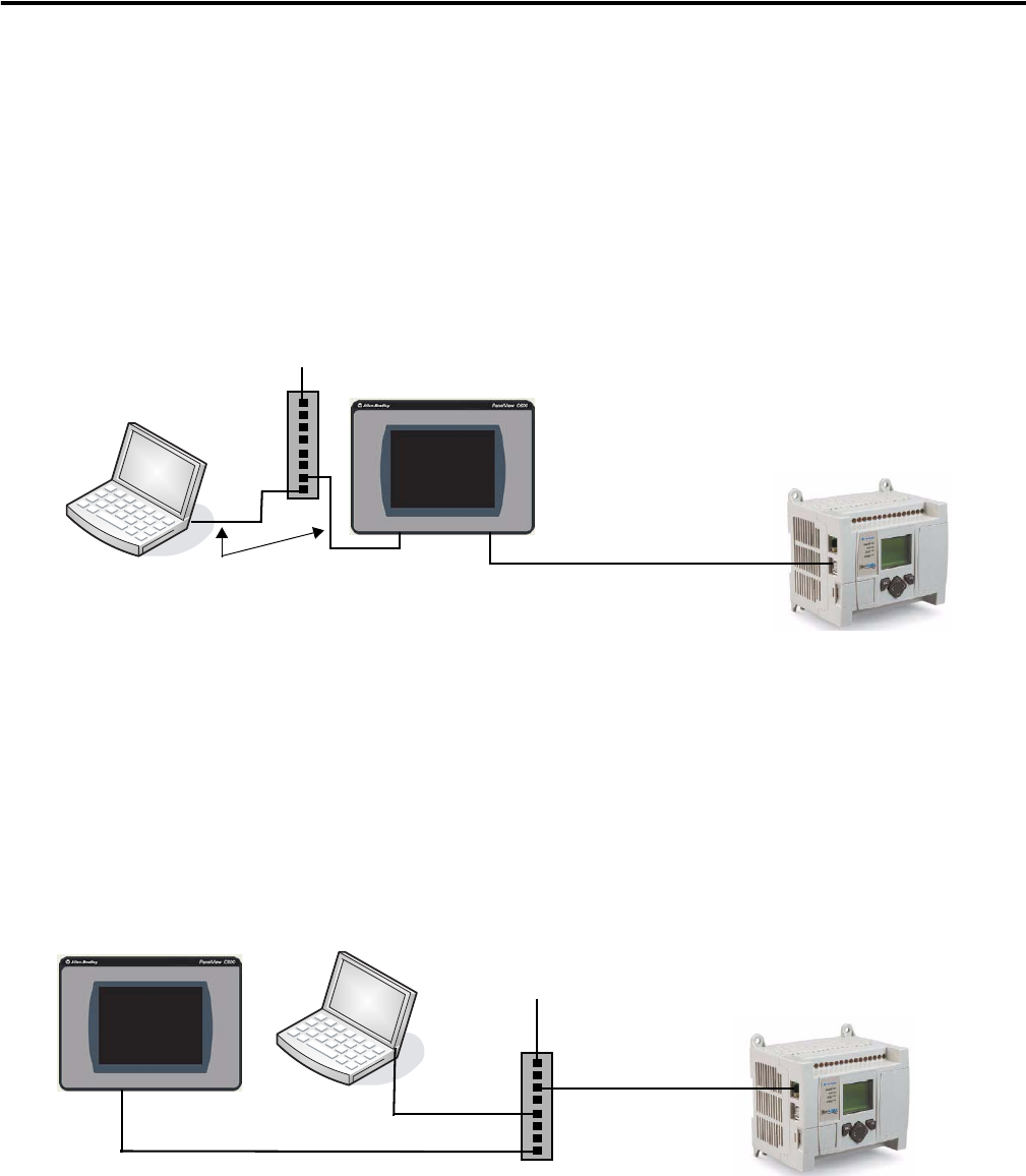
Ethernet Runtime Configuration
The Ethernet configuration shows the Ethernet port of the PanelView Component C600 terminal
connected to the Channel 1 port of the MicroLogix 1100 controller using a standard Ethernet cable or an
Ethernet crossover CAT5 cable, catalog number 2711P-CBL-EX04. The computer, terminal, and controller
are connected to a DHCP-enabled Ethernet network using an Ethernet switch.
Ethernet Cable
Ethernet Port
10/100Base-T
Channel 0 Port
RS-232/485
8-pin Mini DIN
1761-CBL-PM02 Cable
RS-232 Serial Port
9-pin D-shell
To Ethernet DHCP-enabled Network
DF1 Connection
Ethernet Port
10/100Base-T
Channel 1 Port
Ethernet 10/100Base-T
Ethernet Cable
Ethernet Cable
To Ethernet DHCP-enabled Network
Standard Ethernet Cable or
2711P-CBL-EX04 Cable