
Quick Start User Manual
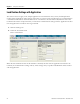
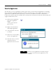

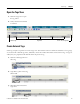
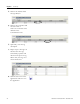
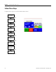
Table Of Contents
- 2711C-QS001F-EN-P PanelView Component HMI Quick Start
- Where to Start
- Preface
- Chapter 1
- Chapter 2
- Chapter 3
- Chapter 4
- Chapter 5
- Chapter 6
- Create the Motor Status Screen
- Introduction
- Before You Begin
- What You Need
- Follow These Steps
- Change the Screen Name
- Change the Grid Attributes
- Create the Start Motor Push Button
- Create the Stop Motor Push Button
- Create the Motor Speed Screen Button
- Create a Goto Config Button
- Create the Motor Control List Selector
- Create the Motor Status Indicators
- Save the Motor Status Screen
- Create the Motor Status Screen
- Chapter 7
- Create the Motor Speed Screen
- Introduction
- Before You Begin
- What You Need
- Follow These Steps
- Create a New Screen
- Create the Motor Status Screen Button
- Create a Numeric Entry Object
- Create a Heading for the Numeric Entry Object
- Create a Increment Decrement Object
- Create Increment Decrement Keys
- Create a Bar Graph
- Create a Bar Graph Scale
- Create Text Labels for the Scale
- Create a Bar Graph Heading
- Create a Numeric Display
- Create a Heading for the Numeric Display
- Update the Motor Speed Screen Button
- Create the Motor Speed Screen
- Chapter 8
- Chapter 9
- Appendix A
- Back Cover
48 Publication 2711C-QS001F-EN-P - November 2010
Chapter 5 Create Tags
4. Click in the Address field
and type B3:0/0.
5. Click in the Controller field
and select PLC-1.
This is the controller name
defined on the
Communication tab.
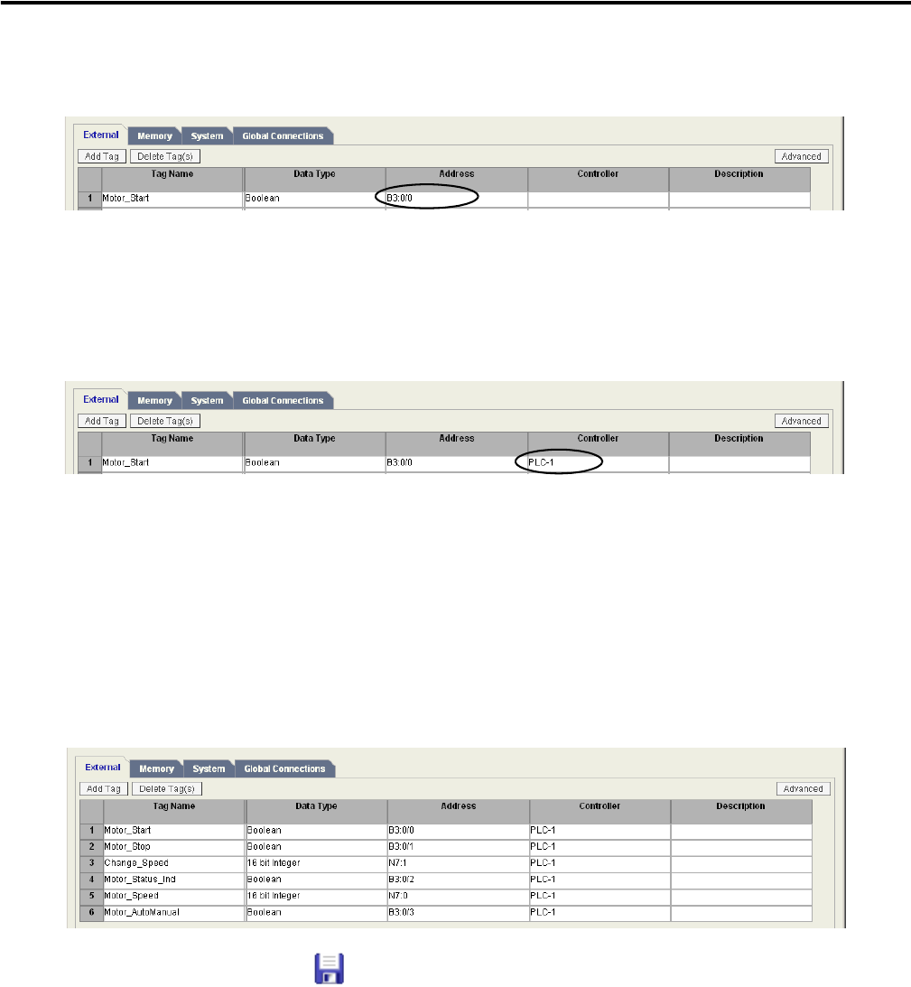
6. Optionally, enter the tag
description.
7. Repeat steps 1 through 6 to
add the other five tags.
Some fields populate with
data from the previous tag.
When done, the Tags view
must look like this.
8. Click the Save icon on the
application toolbar to save
the application.