
Quick Start User Manual
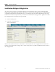
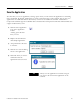

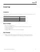
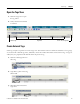
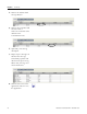
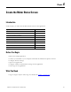
Table Of Contents
- 2711C-QS001F-EN-P PanelView Component HMI Quick Start
- Where to Start
- Preface
- Chapter 1
- Chapter 2
- Chapter 3
- Chapter 4
- Chapter 5
- Chapter 6
- Create the Motor Status Screen
- Introduction
- Before You Begin
- What You Need
- Follow These Steps
- Change the Screen Name
- Change the Grid Attributes
- Create the Start Motor Push Button
- Create the Stop Motor Push Button
- Create the Motor Speed Screen Button
- Create a Goto Config Button
- Create the Motor Control List Selector
- Create the Motor Status Indicators
- Save the Motor Status Screen
- Create the Motor Status Screen
- Chapter 7
- Create the Motor Speed Screen
- Introduction
- Before You Begin
- What You Need
- Follow These Steps
- Create a New Screen
- Create the Motor Status Screen Button
- Create a Numeric Entry Object
- Create a Heading for the Numeric Entry Object
- Create a Increment Decrement Object
- Create Increment Decrement Keys
- Create a Bar Graph
- Create a Bar Graph Scale
- Create Text Labels for the Scale
- Create a Bar Graph Heading
- Create a Numeric Display
- Create a Heading for the Numeric Display
- Update the Motor Speed Screen Button
- Create the Motor Speed Screen
- Chapter 8
- Chapter 9
- Appendix A
- Back Cover
46 Publication 2711C-QS001F-EN-P - November 2010
Chapter 5 Create Tags
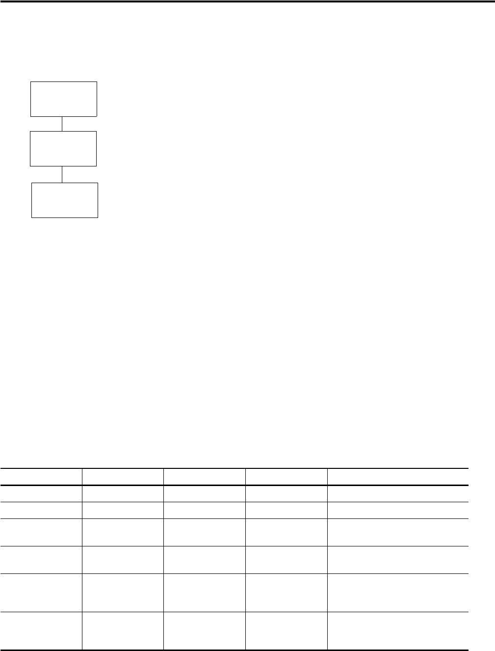
Follow These Steps
Complete these steps to enter application tags.
Review Application Tags
The sample application uses read and write tags to define how objects interact with the addresses of a
MicroLogix 1100 controller. You must create these tags before you can assign them to objects in the
application. Only objects that interact with the controller require a tag. Objects such as screen navigation
buttons, drawings, and screen text do not require tags.
The same tags are used when communicating to a MicroLogix 1100 controller using DF1 or Ethernet
communication.
Refer to this table when entering your application tags.
Application Tags
Tag Name Data Type Tag Address Controller Description
Motor_Start Boolean B3:0/0 PLC_1 Starts the motor.
Motor_Stop Boolean B3:0/1 PLC_1 Stops the motor.
Change_Speed 16 bit integer N7:1 PLC_1 Changes the motor speed to a value
between 0 and 1000 rpm.
Motor_Status_Ind Boolean B3:0/2 PLC_1 Reads the running or stopped status
of the motor.
Motor_Speed 16 bit integer N7:0 PLC_1 Reads the current motor speed. Also
used to trigger an alarm if the speed
rises above 850 or 900 rpm.
Motor_AutoManual Boolean B3:0/3 PLC_1 Changes the motor to auto or manual
mode and also used to read the
current mode of the motor.
page 46
Review
Application Tags
Open the Tags
View
Create
External Tags
page 47
page 47