
Quick Start User Manual
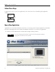
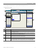
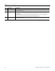
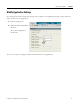

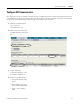
Table Of Contents
- 2711C-QS001F-EN-P PanelView Component HMI Quick Start
- Where to Start
- Preface
- Chapter 1
- Chapter 2
- Chapter 3
- Chapter 4
- Chapter 5
- Chapter 6
- Create the Motor Status Screen
- Introduction
- Before You Begin
- What You Need
- Follow These Steps
- Change the Screen Name
- Change the Grid Attributes
- Create the Start Motor Push Button
- Create the Stop Motor Push Button
- Create the Motor Speed Screen Button
- Create a Goto Config Button
- Create the Motor Control List Selector
- Create the Motor Status Indicators
- Save the Motor Status Screen
- Create the Motor Status Screen
- Chapter 7
- Create the Motor Speed Screen
- Introduction
- Before You Begin
- What You Need
- Follow These Steps
- Create a New Screen
- Create the Motor Status Screen Button
- Create a Numeric Entry Object
- Create a Heading for the Numeric Entry Object
- Create a Increment Decrement Object
- Create Increment Decrement Keys
- Create a Bar Graph
- Create a Bar Graph Scale
- Create Text Labels for the Scale
- Create a Bar Graph Heading
- Create a Numeric Display
- Create a Heading for the Numeric Display
- Update the Motor Speed Screen Button
- Create the Motor Speed Screen
- Chapter 8
- Chapter 9
- Appendix A
- Back Cover
40 Publication 2711C-QS001F-EN-P - November 2010
Chapter 4 Configure Communication
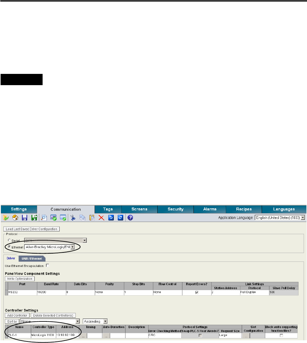
Configure Ethernet Communication
This topic shows how to configure runtime settings to enable Ethernet communication between your
PanelView Component terminal and a MicroLogix 1100 controller. It is not necessary to configure settings
for the terminal if using DHCP-enabled network IP addresses.
1. Click the Communication
tab to open the
Communication view.
2. Select Ethernet under
Protocol.
3. Select Allen-Bradley
Micrologix/ENI from the
pull-down list.
TIP
If the target terminal for an application uses a static IP network address, you would enter the
address on the USB/Ethernet tab.