
Quick Start User Manual
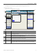
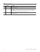
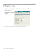

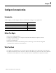
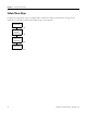
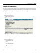
Table Of Contents
- 2711C-QS001F-EN-P PanelView Component HMI Quick Start
- Where to Start
- Preface
- Chapter 1
- Chapter 2
- Chapter 3
- Chapter 4
- Chapter 5
- Chapter 6
- Create the Motor Status Screen
- Introduction
- Before You Begin
- What You Need
- Follow These Steps
- Change the Screen Name
- Change the Grid Attributes
- Create the Start Motor Push Button
- Create the Stop Motor Push Button
- Create the Motor Speed Screen Button
- Create a Goto Config Button
- Create the Motor Control List Selector
- Create the Motor Status Indicators
- Save the Motor Status Screen
- Create the Motor Status Screen
- Chapter 7
- Create the Motor Speed Screen
- Introduction
- Before You Begin
- What You Need
- Follow These Steps
- Create a New Screen
- Create the Motor Status Screen Button
- Create a Numeric Entry Object
- Create a Heading for the Numeric Entry Object
- Create a Increment Decrement Object
- Create Increment Decrement Keys
- Create a Bar Graph
- Create a Bar Graph Scale
- Create Text Labels for the Scale
- Create a Bar Graph Heading
- Create a Numeric Display
- Create a Heading for the Numeric Display
- Update the Motor Speed Screen Button
- Create the Motor Speed Screen
- Chapter 8
- Chapter 9
- Appendix A
- Back Cover
38 Publication 2711C-QS001F-EN-P - November 2010
Chapter 4 Configure Communication
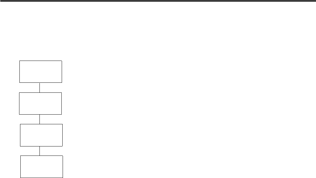
Follow These Steps
Complete the appropriate steps to configure DF1 or Ethernet runtime communication settings for the
PanelView Component terminal and the MicroLogix 1100 controller.
page 39
Configure DF1
Communication
Configure
Ethernet
Communication
page 40
Load Runtime
Settings with
Application
page 42
Save the
Application
page 43