
Quick Start User Manual
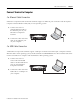
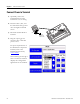
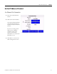
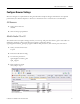
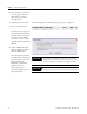
Table Of Contents
- 2711C-QS001F-EN-P PanelView Component HMI Quick Start
- Where to Start
- Preface
- Chapter 1
- Chapter 2
- Chapter 3
- Chapter 4
- Chapter 5
- Chapter 6
- Create the Motor Status Screen
- Introduction
- Before You Begin
- What You Need
- Follow These Steps
- Change the Screen Name
- Change the Grid Attributes
- Create the Start Motor Push Button
- Create the Stop Motor Push Button
- Create the Motor Speed Screen Button
- Create a Goto Config Button
- Create the Motor Control List Selector
- Create the Motor Status Indicators
- Save the Motor Status Screen
- Create the Motor Status Screen
- Chapter 7
- Create the Motor Speed Screen
- Introduction
- Before You Begin
- What You Need
- Follow These Steps
- Create a New Screen
- Create the Motor Status Screen Button
- Create a Numeric Entry Object
- Create a Heading for the Numeric Entry Object
- Create a Increment Decrement Object
- Create Increment Decrement Keys
- Create a Bar Graph
- Create a Bar Graph Scale
- Create Text Labels for the Scale
- Create a Bar Graph Heading
- Create a Numeric Display
- Create a Heading for the Numeric Display
- Update the Motor Speed Screen Button
- Create the Motor Speed Screen
- Chapter 8
- Chapter 9
- Appendix A
- Back Cover
24 Publication 2711C-QS001F-EN-P - November 2010
Chapter 2 Make Terminal Connections
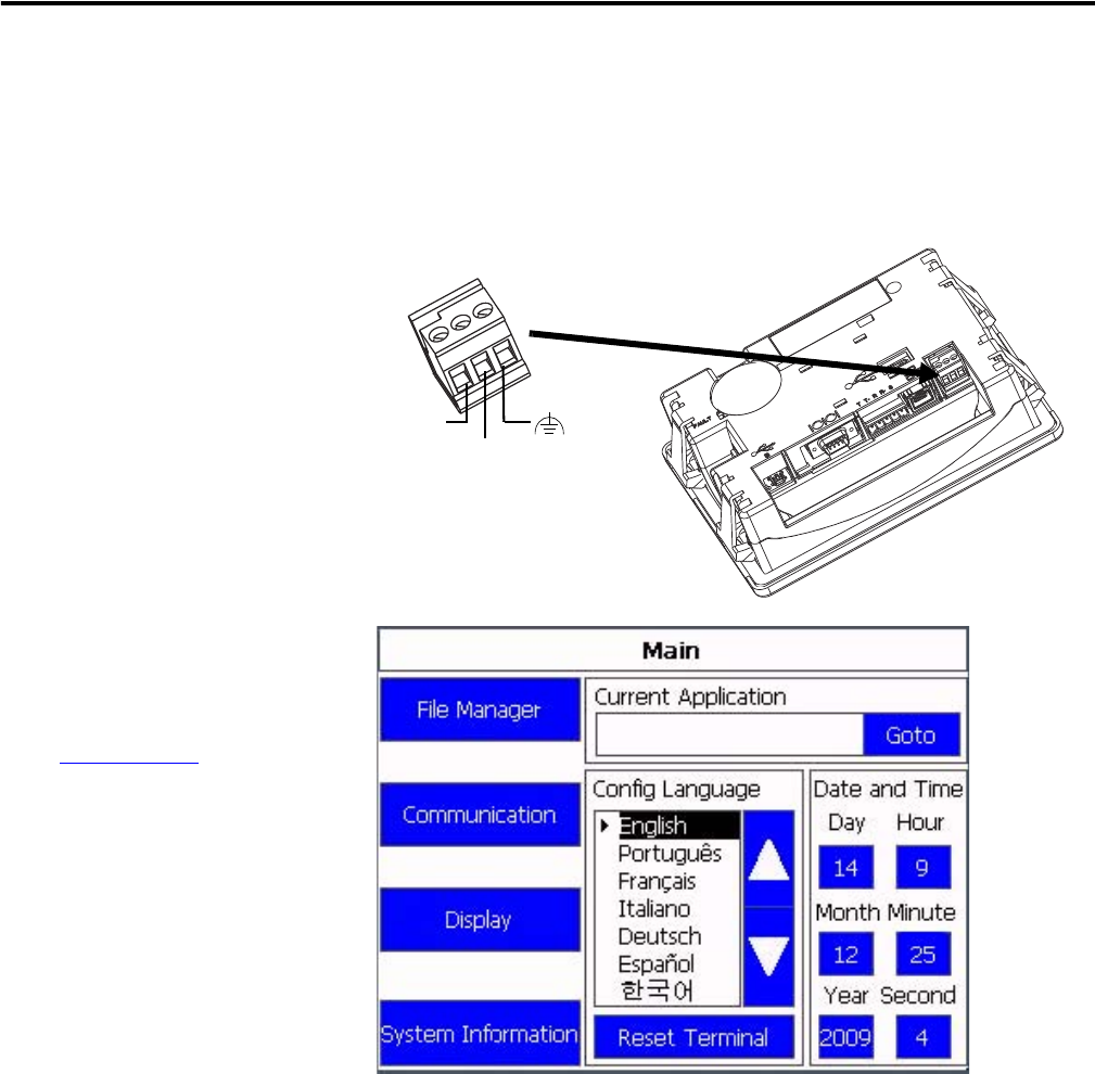
Connect Power to Terminal
1. Optionally, remove the
terminal block from the
terminal for ease of wiring.
2. Insert the DC+, DC-, and
the functional-earth ground
wires and tighten terminal
screws.
3. Re-attach terminal block to
terminal.
4. Plug the 3-prong power
connector into a 24V DC
power source.
For power requirements of
the PanelView Component
terminal, refer to the
installation instructions,
2711C-IN001.
The terminal goes through a
series of self-tests and then
displays the configuration
application for the terminal.
DC+
DC-
Functional
Earth Ground
to Ground Bus