
Quick Start User Manual


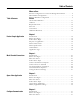
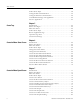

Table Of Contents
- 2711C-QS001F-EN-P PanelView Component HMI Quick Start
- Where to Start
- Preface
- Chapter 1
- Chapter 2
- Chapter 3
- Chapter 4
- Chapter 5
- Chapter 6
- Create the Motor Status Screen
- Introduction
- Before You Begin
- What You Need
- Follow These Steps
- Change the Screen Name
- Change the Grid Attributes
- Create the Start Motor Push Button
- Create the Stop Motor Push Button
- Create the Motor Speed Screen Button
- Create a Goto Config Button
- Create the Motor Control List Selector
- Create the Motor Status Indicators
- Save the Motor Status Screen
- Create the Motor Status Screen
- Chapter 7
- Create the Motor Speed Screen
- Introduction
- Before You Begin
- What You Need
- Follow These Steps
- Create a New Screen
- Create the Motor Status Screen Button
- Create a Numeric Entry Object
- Create a Heading for the Numeric Entry Object
- Create a Increment Decrement Object
- Create Increment Decrement Keys
- Create a Bar Graph
- Create a Bar Graph Scale
- Create Text Labels for the Scale
- Create a Bar Graph Heading
- Create a Numeric Display
- Create a Heading for the Numeric Display
- Update the Motor Speed Screen Button
- Create the Motor Speed Screen
- Chapter 8
- Chapter 9
- Appendix A
- Back Cover
2Publication 2711C-QS001F-EN-P - November 2010 2
Important User Information
Solid state equipment has operational characteristics differing from those of electromechanical equipment. Safety Guidelines for
the Application, Installation and Maintenance of Solid State Controls (publication SGI-1.1
available from your local Rockwell
Automation sales office or online at http://literature.rockwellautomation.com
) describes some important differences between
solid state equipment and hard-wired electromechanical devices. Because of this difference, and also because of the wide variety of
uses for solid state equipment, all persons responsible for applying this equipment must satisfy themselves that each intended
application of this equipment is acceptable.
In no event will Rockwell Automation, Inc. be responsible or liable for indirect or consequential damages resulting from the use or
application of this equipment.
The examples and diagrams in this manual are included solely for illustrative purposes. Because of the many variables and
requirements associated with any particular installation, Rockwell Automation, Inc. cannot assume responsibility or liability for
actual use based on the examples and diagrams.
No patent liability is assumed by Rockwell Automation, Inc. with respect to use of information, circuits, equipment, or software
described in this manual.
Reproduction of the contents of this manual, in whole or in part, without written permission of Rockwell Automation, Inc., is
prohibited.
Throughout this manual, when necessary, we use notes to make you aware of safety considerations.
Rockwell Automation, Allen-Bradley, TechConnect, PanelView, PanelView Component, and MicroLogix are trademarks of Rockwell Automation, Inc.
Trademarks not belonging to Rockwell Automation are property of their respective companies.
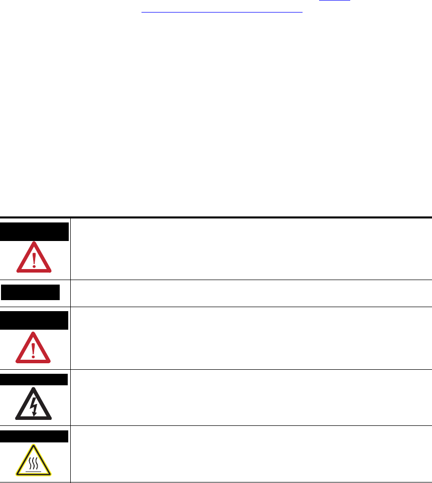
WARNING
Identifies information about practices or circumstances that can cause an explosion in a
hazardous environment, which may lead to personal injury or death, property damage, or
economic loss.
IMPORTANT
Identifies information that is critical for successful application and understanding of the product.
ATTENTION
Identifies information about practices or circumstances that can lead to personal injury or death,
property damage, or economic loss. Attentions help you identify a hazard, avoid a hazard, and
recognize the consequence
SHOCK HAZARD
Labels may be on or inside the equipment, for example, a drive or motor, to alert people that
dangerous voltage may be present.
BURN HAZARD
Labels may be on or inside the equipment, for example, a drive or motor, to alert people that
surfaces may reach dangerous temperatures.