PanelView Component HMI Terminals Quick Start (Catalog Numbers 2711C-F2M, 2711C-K2M, 2711C-T3M, 2711C-K3M, 2711C-T6M, 2711C-T6C, 2711C-T6T, 2711C-T10C)
Important User Information Solid state equipment has operational characteristics differing from those of electromechanical equipment. Safety Guidelines for the Application, Installation and Maintenance of Solid State Controls (publication SGI-1.1 available from your local Rockwell Automation sales office or online at http://literature.rockwellautomation.com) describes some important differences between solid state equipment and hard-wired electromechanical devices.
Where to Start Chapter 1 Review Sample Application Chapter 2 Make Terminal Connections Chapter 3 Open a New Application Chapter 4 Configure Communication Chapter 5 Create Tags Chapter 6 Create the Motor Status Screen Chapter 7 Create the Motor Speed Screen Chapter 8 Create Alarms Chapter 9 Validate and Run Application 3Publication 2711C-QS001F-EN-P - November 2010 3
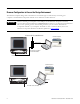
Browser Configuration to Access the Design Environment The PanelView Explorer design-time environment is accessed through a web browser by connecting your computer to the PanelView Component terminal over an Ethernet or USB connection. IMPORTANT Before connecting your computer to the USB port of the PanelView Component terminal, you must first install the "PanelView USB RNDIS Device" driver on a computer with the Windows XP or Vista operating system.
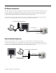
DF1 Runtime Configuration The DF1 configuration shows the PanelView Component C600 terminal connected to the MicroLogix 1100 controller using the 1761-CBL-PM02 cable. One end of the cable connects to the RS-232 serial port of the terminal and the other end connects to the Channel 0 port of the controller. The terminal and computer are connected to a DHCP-enabled Ethernet network using an Ethernet switch. You can substitute another MicroLogix model in place of the MicroLogix 1100 controller.
Notes: 6 Publication 2711C-QS001F-EN-P - November 2010
Table of Contents Where to Start Table of Contents Browser Configuration to Access the Design Environment . . . . . . . . . 4 DF1 Runtime Configuration . . . . . . . . . . . . . . . . . . . . . . . . . . . . . . . . . . 5 Ethernet Runtime Configuration. . . . . . . . . . . . . . . . . . . . . . . . . . . . . . . 5 Preface About This Publication . . . . . . . . . . . . . . . . . . . . . . . . . . . . . . . . . . . . . 11 Audience . . . . . . . . . . . . . . . . . . . . . . . . . . . . . . . . . . . . . .
Table of Contents Follow These Steps . . . . . . . . . . . . . . . . . . . . . . . . . . . . . . . . . . . . . . . . 38 Configure DF1 Communication . . . . . . . . . . . . . . . . . . . . . . . . . . . . . . 39 Configure Ethernet Communication. . . . . . . . . . . . . . . . . . . . . . . . . . . 40 Load Runtime Settings with Application . . . . . . . . . . . . . . . . . . . . . . . 42 Save the Application. . . . . . . . . . . . . . . . . . . . . . . . . . . . . . . . . . . . . . . .
Table of Contents Create a Numeric Display . . . . . . . . . . . . . . . . . . . . . . . . . . . . . . . . . . . 84 Create a Heading for the Numeric Display. . . . . . . . . . . . . . . . . . . . . . 85 Update the Motor Speed Screen Button . . . . . . . . . . . . . . . . . . . . . . . . 86 Chapter 8 Create Alarms Introduction . . . . . . . . . . . . . . . . . . . . . . . . . . . . . . . . . . . . . . . . . . . . . . 87 Before You Begin. . . . . . . . . . . . . . . . . . . . . . . . . . . . . . . . . . .
Table of Contents Notes: 10 Publication 2711C-QS001F-EN-P - November 2010
Preface About This Publication Use this manual to create a sample application to run in a PanelView Component HMI terminal. You will use the design environment of the PanelView Explorer software to create the application.
Required Software To complete this quick start, the following software is required: • PanelView Explorer software, V1.0 or higher This software is resident on your PanelView Component terminal. Separate software is not required. After establishing an Ethernet connection between your terminal and computer, you can launch the PanelView Explorer software from your web browser by entering the IP address of the terminal.
Parts List This quick start uses the following hardware. Quantity Catalog Number Description 1 2711C-T6C PanelView Component C600 touch-screen, color terminal 1 1763-L16xxx MicroLogix 1100 controller 2 or 3 Standard Ethernet cable or Standard Ethernet cable or crossover Ethernet cable 2711P-CBL-EX04 This cable is used to connect the terminal to the computer using the Ethernet port of the terminal for design-time configuration.
Additional Resources Resource Description PanelView Explorer online help Provides information on how to use the design environment of the PanelView Explorer software. PanelView Component HMI Terminal Installation Instructions, publication 2711C-IN001 Provides information on how to install the PanelView Component terminal in a panel.
Chapter 1 Review Sample Application Introduction In this chapter, you will review the purpose of the sample application and the actual screens in the application. Topic Page Purpose of Application 16 Motor Status Screen 17 Motor Speed Screen 18 Alarm Banner 19 Application Tags 20 Before You Begin Review the where to start section and preface.
Chapter 1 Review Sample Application Follow These Steps Review the sample application. Purpose of Application Alarm Banner page 16 Motor Status Screen page 19 Application Tags page 17 page 20 Motor Speed Screen page 18 Purpose of Application The sample application contains screens and objects to control and monitor the status of a motor. The PanelView Component terminal reads and writes data to a MicroLogix controller using: • DF1 point-to-point communication or • Ethernet communication.
Review Sample Application Chapter 1 Motor Status Screen The Motor Status screen is one of two screens in the application. It is the startup screen when the application is loaded and running in the terminal. The Motor Status screen lets you: • • • • • start and stop a motor. set the motor control to auto or manual mode. monitor the start/stop status and the auto/manual mode of the motor. navigate to the Motor Speed screen. navigate to the configuration mode screens of the terminal.
Chapter 1 Review Sample Application Motor Speed Screen The Motor Speed screen lets you: • • • • enter a new motor speed. increase or decrease the motor speed in increments. monitor the motor speed. navigate to the Motor Status screen. 1 6 5 2 3 4 Objects on the Motor Speed Screen # This object Performs this function 1 Numeric Entry Opens a numeric keypad, when selected, to change the speed of the motor to a value between 0 and 1000 rpm. This object works only in manual mode.
Review Sample Application Chapter 1 Alarm Banner The alarm banner is a global display that pops up over the Motor Status or Motor Speed screen when an alarm is triggered. The alarm banner lets you: • • • • read a message associated with a triggered alarm. clear the alarm banner from the screen. acknowledge an alarm and clear the banner. close the banner.
Chapter 1 Review Sample Application Application Tags The sample application uses read and write tags to define how objects interact with addresses in the MicroLogix 1100 controller. The tags read or write data to a bit or integer file. Objects that do not read or write to a controller address such as screen buttons or headings do not require a tag. The same tags are used for DF1 or Ethernet communication.
Chapter 2 Make Terminal Connections Introduction In this chapter, you will connect a PanelView Component C600 terminal to your computer, connect power, get the IP address of terminal, and launch the PanelView Explorer software.
Chapter 2 Make Terminal Connections • Allen-Bradley PanelView USB remote NIDS Network Device driver installed on computer for USB port connection only. This driver does not work with the Windows 2000 operating system. See the PanelView Component Terminal User Manual, publication 2711C-UM001, for details on how to install this driver. Follow These Steps Complete these steps to connect your computer to a PanelView Component terminal and launch the PanelView Explorer software.
Make Terminal Connections Chapter 2 Connect Terminal to Computer For Ethernet Cable Connection PanelView Component C600 and C1000 terminals support an Ethernet port connection and will require a computer with the Windows 2000, XP, or Vista operating system. 1. Connect one end of a standard Ethernet cable to the Ethernet port on your PanelView Component terminal. 2. Connect the other end of the cable to the Ethernet port on your computer.
Chapter 2 Make Terminal Connections Connect Power to Terminal 1. Optionally, remove the terminal block from the terminal for ease of wiring. 2. Insert the DC+, DC-, and the functional-earth ground wires and tighten terminal screws. 3. Re-attach terminal block to terminal. 4. Plug the 3-prong power connector into a 24V DC power source. DC+ DC- Functional Earth Ground to Ground Bus For power requirements of the PanelView Component terminal, refer to the installation instructions, 2711C-IN001.
Make Terminal Connections Chapter 2 Get the IP Address of Terminal For Ethernet Port Connection 1. Press the Communication button. 2. Write down the IP address. You will need this IP address when launching PanelView Explorer from your Internet browser. If you are not using an IP address from a DHCP enabled network, then contact your network administrator on what static IP address to use. 3. Click Main to return to the Main configuration screen.
Chapter 2 Make Terminal Connections Launch PanelView Explorer Internet Explorer 7 Web Browser, or Mozilla Firefox 2.0 or 3.0 Web Browser 1. Launch your Internet browser. 2. Type the IP address of your PanelView Component terminal in the web address field. This establishes a local Ethernet connection between your terminal and computer. The PanelView Explorer Startup Window opens. From here you access the design environment to create applications.
Make Terminal Connections Chapter 2 Configure Browser Settings Browser changes are required before using the PanelView Explorer design environment. For optimal performance, the Internet Explorer 7 browser or the Firefox 2.0 or 3.0 browser is recommended. All Browsers 1. Verify that cookies are enabled. 2. Turn off the pop-up blocker. Mozilla Firefox 2.0 or 3.0 The Firefox browser requires changes before you can copy and paste data from a grid or state editor in PanelView Explorer to Excel.
Chapter 2 Make Terminal Connections 5. If the preference name does not exist, right-click in the main window and select New>Boolean. 6. Type this preference name. signed.applets.codebase_principal_support 7. Enter true for the Value. The first time you copy and paste data from a PanelView Explorer grid or state editor to Excel, a security dialog will open to alert you that a script is requesting enhanced abilities. 8. Check the Remember this decision checkbox, and then click the Allow button.
Make Terminal Connections Chapter 2 Internet Explorer 6 and 7 The Windows clipboard is used to copy and paste data in applications such as Excel and text documents. To copy and paste data between PanelView Explorer and Windows applications, you must enable your browser to access the Windows clipboard. 1. Make sure Internet Explorer is open. Internet Explorer 7 2. Select Tools>Internet Options. 3. Click the Security tab. 4. Click Local Intranet, then the Custom Level button. 5.
Chapter 2 Make Terminal Connections 6. Click the Sites button. Internet Explorer 7 7. Click the Advanced button. 8. In the Add this website to the zone field, enter the IP address of your terminal, in the format http://10.90.95.13. 9. Click the Add button. 10. Click OK until you exit the Internet Options dialog.
Chapter 3 Open a New Application Introduction In this chapter, you will open a new application and modify settings that are global to the application. Topic Page Open a New Application 32 Modify Application Settings 35 Before You Begin • Review the sample application. • Connect your terminal to your computer and launch the PanelView Explorer software. • Configure browser settings. What You Need PanelView Explorer Startup window launched in your web browser.
Chapter 3 Open a New Application Follow These Steps Complete these steps to open a new application, review the screens view, and modify global application settings. Open a New Application page 32 Modify Application Settings page 35 Open a New Application Applications are created with default file names that you can change when saving the application. The default file name is PVcApplication1. The number automatically increments as you create new applications. 1.
Open a New Application Chapter 3 The design environment opens in a separate window, showing the Screens view. 2. Review areas of screen. This is where you will spend most of your time. 3 1 2 7 4 5 8 6 9 # Screen area Description 1 Navigation tabs Provides access to the different functional areas of an application. 2 Application toolbar Provides common tools that are available to all views of the application. Drag your mouse over each tool to see the purpose of each tool.
Chapter 3 Open a New Application # Screen area Description 7 Screen toolbar Contains tools that operate on selected objects in the screen workspace. Also contains a tool for turning the screen grid on or off. 8 Properties panel Contains panels of properties to configure the appearance, navigation, common properties, or connection tags of a selected object. Panels vary for each object. Click the cursor on a tab to open or close a panel.
Open a New Application Chapter 3 Modify Application Settings The Settings tab contains design-time settings that are global to an application. Changes made on this tab affect all screens in the application. 1. Click the Settings tab. 2. Check the Default Font Bold checkbox. All text in the application will be bold. You are now ready to configure runtime communication for the application.
Chapter 3 Open a New Application Notes: 36 Publication 2711C-QS001F-EN-P - November 2010
Chapter 4 Configure Communication Introduction In this chapter, you will configure runtime communication settings for your application. Topic Page Configure DF1 Communication 39 Configure Ethernet Communication 40 Load Runtime Settings with Application 42 Save the Application 43 Before You Begin • • • • • Review the sample application. Connect your terminal to your computer and launch the PanelView Explorer software. Configure browser settings. Open a new application.
Chapter 4 Configure Communication Follow These Steps Complete the appropriate steps to configure DF1 or Ethernet runtime communication settings for the PanelView Component terminal and the MicroLogix 1100 controller.
Configure Communication Chapter 4 Configure DF1 Communication This topic shows how to configure runtime settings to enable DF1 point-to-point communication between your PanelView Component terminal and a MicroLogix 1100 controller. The DF1 settings for the PanelView Component terminal match the default settings of the MicroLogix controller. 1. Click the Communication tab to open the Communication view. 2. Select Serial under Protocol and DF1 from the pull-down list. 3.
Chapter 4 Configure Communication Configure Ethernet Communication This topic shows how to configure runtime settings to enable Ethernet communication between your PanelView Component terminal and a MicroLogix 1100 controller. It is not necessary to configure settings for the terminal if using DHCP-enabled network IP addresses. TIP If the target terminal for an application uses a static IP network address, you would enter the address on the USB/Ethernet tab. 1.
Configure Communication Chapter 4 4. Under Controller Settings: a. Accept the default name PLC-1. a. Verify that MicroLogix 1100 is selected in the Controller Type field. b. Type the IP address of the controller in the Address field.
Chapter 4 Configure Communication Load Runtime Settings with Application This section does not apply to the sample application but is information that you may find helpful when creating future applications. There may be times when you want to load an application on a terminal that has a static IP network address. Static IP addresses for a terminal are entered on the USB/Ethernet tab of the Communication tab.
Configure Communication Chapter 4 Save the Application The first time you save an application, a dialog opens where you can rename the application to something more meaningful. By default, applications are saved to internal storage of the terminal. You can also save applications to a USB flash drive or SD memory card if one is loaded in the terminal. All PanelView Component terminals support a USB flash drive. The PanelView Component C600 and C1000 terminals also support an SD memory card. 1.
Chapter 4 Configure Communication Notes: 44 Publication 2711C-QS001F-EN-P - November 2010
Chapter 5 Create Tags Introduction In this chapter, you will create tags used by the sample application. You must create tags before you can assign them to objects. Topic Page Review Application Tags 46 Open the Tags View 47 Create External Tags 47 Before You Begin • • • • • Review the sample application. Connect your terminal to your computer and launch the PanelView Explorer software. Configure browser settings. Open a new application.
Chapter 5 Create Tags Follow These Steps Complete these steps to enter application tags. Review Application Tags page 46 Open the Tags View page 47 Create External Tags page 47 Review Application Tags The sample application uses read and write tags to define how objects interact with the addresses of a MicroLogix 1100 controller. You must create these tags before you can assign them to objects in the application. Only objects that interact with the controller require a tag.
Create Tags Chapter 5 Open the Tags View 1. Click the Tags tab to open the tag editor. 2. Verify that the External tab is selected. Adds a tag Tag fields Shows more tag fields Create External Tags Each tag occupies a separate row in the Tags view. The fields in each row define the attributes of a tag. Tags are created with a default tag name, TAG0001, where the number increments with each new tag. As tags are added, they are populated with defaults from the previous tag. 1.
Chapter 5 Create Tags 4. Click in the Address field and type B3:0/0. 5. Click in the Controller field and select PLC-1. This is the controller name defined on the Communication tab. 6. Optionally, enter the tag description. 7. Repeat steps 1 through 6 to add the other five tags. Some fields populate with data from the previous tag. When done, the Tags view must look like this. 8. Click the Save icon on the application toolbar to save the application.
Chapter 6 Create the Motor Status Screen Introduction In this chapter, you will create the Motor Status screen of the application.
Chapter 6 Create the Motor Status Screen Follow These Steps Complete these steps to create the Motor Status screen.
Create the Motor Status Screen Chapter 6 Change the Screen Name New applications open with the first screen created. Each screen is created with a default name, Screen_NN, where NN is a number from 1 to 99. The first screen is named Screen_1. You can rename the screen using a maximum of 50 characters. 1. Click the Screens tab to open the Screens view. 2. Verify the screen border is highlighted indicating the screen is selected. You can modify screen properties as long as nothing on the screen is selected.
Chapter 6 Create the Motor Status Screen Change the Grid Attributes For easier alignment and positioning of screen objects, you can adjust the grid settings of a screen. The settings will vary with each PanelView Component terminal size. 1. In the toolbar above the screen, scroll to the right. 2. Click the Toggle Snap to Grid tool to display the screen grid. 3. Under Properties, click the cursor next to Screen. 4. Change the value from 10 to 5 in the Horizontal Grid Spacing field. 5.
Create the Motor Status Screen Chapter 6 3. Resize the button by clicking a corner handle and dragging diagonally or move the button by dragging it on the screen. 4. Open the States editor. a. Double-click object; b. Or, right-click object and select Edit States; c. Or, click the Edit Properties button on the Appearance tab of the Properties panel. Each row is a state with a default value, text, and other format options. Move the scroll bar to view all the fields. 5. Edit state 1 (row 1). a.
Chapter 6 Create the Motor Status Screen 9. Resize object if needed. An asterisk * appears if the text exceeds the size of the object. 10. On the Appearance tab, set the Border Width to 6. 11. Assign tags to the Start Motor push button. a. Make sure the push button is selected. b. Click the cursor next to the Connections tab on the Properties panel. c. Click in the Write Tag field and select Motor_Start. 12. Verify the view the object on the terminal.
Create the Motor Status Screen Chapter 6 4. Move the pasted button to the right of the original push button. 5. Double-click the object to open the States editor. 6. Edit state 1 (row 1). a. Replace the text with STOP MOTOR. b. Select red as the Background Color. c. Select white as the Text Color. 7. Edit state 2 (row 2). a. Replace the text with MOTOR STOPPED. b. Select red as the Background Color. c. Select white as the Text Color. State 1 State 2 8. Click row 1 to make this the displayed state. 9.
Chapter 6 Create the Motor Status Screen Create the Motor Speed Screen Button The Motor Speed (Goto Screen) button lets you open the Motor Speed screen when the button is pressed. You will create the button now, but will not link it to the Motor Speed screen until later, page 86. IMPORTANT The Motor Speed screen must be created before you can assign it to the button. 1. Open the Entry tab of the object palette and scroll until you see the Goto Screen button. 2.
Create the Motor Status Screen Chapter 6 4. Resize the Goto Screen button if necessary to fit the text. 5. Verify the view of the Motor Speed (Goto Screen) button on the terminal.
Chapter 6 Create the Motor Status Screen Create a Goto Config Button The Goto Config button lets you access the configuration mode screens of the terminal when the button is pressed at runtime. 1. Click the Advanced cursor on the object palette and scroll down until you see the Goto Config button. 2. Drag the Goto Config button to the left of the Motor Speed button and resize. 3. On the Appearance tab of the Properties panel: a. Change Goto Config to CONFIG SCREEN in the Text field. b.
Create the Motor Status Screen Chapter 6 Create the Motor Control List Selector The motor control list selector lets you switch the motor between manual and automatic mode. 1. Open the Entry tab of the object palette. 2. Drag the List Selector object to the area above the Start Motor and Stop Motor push buttons. 3. Double-click the object to open the States editor. The list selector is created with four states. This example uses only two.
Chapter 6 Create the Motor Status Screen 4. Select row 3, hold down the Shift key, and select row 4. 5. Click the Delete button. 6. Edit state 1 (row 1). a. Replace the Item1 text with AUTOMATIC. b. Set the Font Size to 17. c. Click the ... button in the Alignment field, and select Center Left. Scroll to the right to see all the fields. 7. Edit state 2 (row 2). a. Type 0 in the Value field. b. Replace the Item2 text with MANUAL. c. Set the Font Size to 17. d. Select Center Left in the Alignment field. 8.
Create the Motor Status Screen Chapter 6 10. On the Appearance tab of the Properties panel: a. Select White as the List Selection Text Color. b. Select Black as the List Selection Background Color. c. Change the Border Width to 6. d. Set the Border Style to Raised. 11. On the List tab of the Properties panel, set the Number of Visible Rows to 2. 12. On the Connections tab, select Motor_AutoManual for the Write tag and the Indicator tag. 13. Resize the list selector if necessary. 14.
Chapter 6 Create the Motor Status Screen Create List Keys for the Motor Control List Selector Terminals with a touch screen, or without an attached keyboard, require the up and down list keys on the screen to move the cursor in the list, and the Enter key to make a selection. List keys 1. Open the Entry tab of the object palette and scroll down until you see the Key object. 2. Drag the Key object below the list selector and to the left. 3. Resize the object. 4. Make two copies of the Key object. a.
Create the Motor Status Screen Chapter 6 6. Modify the key type of the pasted key objects. a. Select one of the pasted key objects. b. Open the Navigation tab of the Properties panel. c. Select Down as the Key Type. d. Select the other pasted key object. e. Select Enter as the Key Type. 7. Verify the view of the objects on the terminal. Create a Heading for the Motor Control List Selector 1. Open the Drawing Tools tab of the object palette. 2. Drag the Text tool above the list selector object.
Chapter 6 Create the Motor Status Screen 3. On the Appearance tab: a. Type SELECT MODE in the Text box. b. Set the Font Size to 16. c. Check the Font Underline checkbox. d. Set the Border Style to None. 4. Resize the object to fit the text. Create the Motor Status Indicators The Motor Status box contains two multistate indicators. The Mode indicator shows whether the motor is in Auto or Manual mode. The Status indicator shows whether the motor is running or stopped. Create the Mode Indicator 1.
Create the Motor Status Screen Chapter 6 3. Double-click the object to open the States editor. The indicator is created with four states. This example uses only two. 4. Delete rows 3 and 4. 5. Edit state 1 (row 1). a. Accept 0 as the Value. b. Replace the MultiState0 text with MANUAL. c. Select yellow as the Background Color. d. Select black as the Text Color. 6. Edit state 2 (row 2). a. Accept 1 as the Value. b. Replace the Multistate1 text with AUTO. c. Select yellow as the Background Color. d.
Chapter 6 Create the Motor Status Screen Create a Heading for the Mode Indicator 1. Open the Drawing Tools tab of the object palette. 2. Drag the Text tool above the Mode indicator. 3. On the Appearance tab: a. Type MODE in the Text box. b. Set the Font Size to 16. c. Check the Font Underline checkbox. d. Set the Border Style to None. Scroll down to see all the properties. 4. Resize the object to fit the text.
Create the Motor Status Screen Chapter 6 Create the Status Indicator 1. Select the Mode indicator you just created. 2. Click the Copy tool or press Ctrl+C. 3. Click the Paste tool or press Ctrl+V. 4. Move the pasted object to the right of the original indicator object. 5. Double-click the pasted object to open the States editor. 6. Edit state 1 (row 1). a. Replace the MANUAL text with Stopping. b. Select red as the Background Color. c. Accept black as the Text Color. d. Check the Font Italics checkbox.
Chapter 6 Create the Motor Status Screen 8. Click OK to close the editor. 9. On the Connections tab of the Properties panel, select Motor_Status_Ind as the Read Tag. 10. Resize and move object as needed.
Create the Motor Status Screen Chapter 6 Create a Heading for the Status Indicator 1. Select the heading for the Mode Indicator. 2. Copy and paste the MODE heading. 3. Move the pasted heading to the right above the status indicator. 4. On the Appearance tab, replace the MODE text with STATUS. 5. Resize object to fit text. Create a Border Around the Indicators 1. Drag the Border tool from the Drawing Tools tab to the area of the indicators. 2.
Chapter 6 Create the Motor Status Screen Create a Heading for the Motor Status Indicators 1. Drag the Text tool above the border just created. 2. On the Appearance tab: a. Type MOTOR STATUS in the Text box. b. Set the Font Size to 16. c. Check the Font Underline checkbox. d. Set the Border Style to None. 3. Resize and move as the object as needed. Save the Motor Status Screen You have just completed one of the application screens. Click the Save icon on the application toolbar.
Chapter 7 Create the Motor Speed Screen Introduction In this chapter, you will create and design the Motor Speed screen in the application.
Chapter 7 Create the Motor Speed Screen What You Need • Tags to assign to objects. These tags were defined in the Tags view. Follow These Steps Complete these steps to create the Motor Speed screen.
Create the Motor Speed Screen Chapter 7 Create a New Screen 1. Click the Add button in the Screen List to add a new screen. Screen 2 is added to the list with a default name. 2. On the Screen tab of the Properties panel, change the Horizontal and Vertical Grid Spacing from 10 to 5 and press Enter. The screen grid is updated. 3. Open the Common tab of the Properties panel. 4. In the Name box, type MOTOR SPEED and press Enter. The name appears in the Screen List and above the screen workspace.
Chapter 7 Create the Motor Speed Screen Create the Motor Status Screen Button A copy and paste operation copies the Motor Speed (Goto Screen) button from the Motor Status screen to the Motor Speed screen. 1. Click on MOTOR STATUS in the Screen List to open the screen. 2. Select the MOTOR SPEED button. 3. Click the Copy tool or press Ctrl+C. 4. Click on MOTOR SPEED in the Screen List. 5. Click in the screen area. 6. Click the Paste tool or press Ctrl+V to paste the screen button.
Create the Motor Speed Screen Chapter 7 Create a Numeric Entry Object The numeric entry object lets you change the speed of the motor in manual mode by entering an integer value. The object does not display a value until runtime. 1. Open the Entry tab of the object palette. 2. Drag the Numeric Entry object to the left side of the screen. 3. Resize the object. 4. On the Appearance tab of the Properties panel: a. Change the Border Width to 6. b. Set the Border Style to Raised. 5. Open the Format tab: a.
Chapter 7 Create the Motor Speed Screen Create a Heading for the Numeric Entry Object This topic shows how to create a heading above the numeric entry object. 1. Open the Drawing Tools tab of the object palette. 2. Drag the Text object above the numeric entry object. 3. Resize the object. 4. On the Appearance tab: a. Type ENTER SPEED in the Text box. b. Set the Font Size to 16. c. Check the Font Underline checkbox. d. Set the Border Style to None. Scroll down to see all the properties. 5.
Create the Motor Speed Screen Chapter 7 Create a Increment Decrement Object The numeric increment decrement object lets you increase or decrease the rpm speed of the motor in manual mode using small or large steps when a key is pressed. The object does not display a value until runtime. 1. Open the Entry tab of the object palette. 2. Drag the Numeric Increment Decrement object below the numeric entry object. 3. Resize object as needed. 4. On the Format tab of the Properties panel: a.
Chapter 7 Create the Motor Speed Screen Create Increment Decrement Keys Keys are used to increase or decrease the motor speed displayed in the numeric increment decrement object. The double arrows increase or decrease the speed in 10 rpm increments. The single arrows increase or decrease the speed in 1 rpm increments. 1. Open the Entry tab of the object palette. 2. Drag the Key object below the increment decrement object on the left side. 3. Resize the object. 4.
Create the Motor Speed Screen Chapter 7 8. Click on the Up key just created, then press Ctrl+C then Ctrl+V to copy and paste the key. 9. Move the pasted object to right of the second key. 10. On the Navigation tab, select Down as the Key Type. 11. Click on the Down key just created, then copy and paste the key. 12. Move the pasted object to right of the third key. 13. On the Navigation tab, select Page Down as the Key Type.
Chapter 7 Create the Motor Speed Screen Create a Bar Graph The bar graph monitors and displays the speed of the motor in a graphic form. 1. Open the Display tab of the object palette. 2. Drag the Bar Graph object to the right side of the screen. 3. Resize the bar graph. 4. On the Appearance tab, set the Background Fill Style to Crosshatch. 5. On the Bar tab: a. Set the Maximum Value to 1000. b. Select Bottom for the Fill From Direction. 6. On the Connections tab, select Motor_Speed as the Read Tag.
Create the Motor Speed Screen Chapter 7 Create a Bar Graph Scale 1. On the Display tab of the object palette, drag the Linear Scale object to the screen. 2. On the Appearance tab of the Properties panel select Left as the Tick Mark Direction. 3. Resize and move the scale to the left side of the bar graph.
Chapter 7 Create the Motor Speed Screen Create Text Labels for the Scale 1. Open the Drawing Tools tab of the object palette. 2. Drag the Text tool next to the linear scale. 3. On the Appearance tab of the Properties panel: a. Type 1000 in the Text field. b. Set the Border Style to None. Scroll down to see all the properties. 4. Resize the text object and place it next to the top tick-mark of the scale. 5. Press Ctrl+C then Ctrl+V to copy and paste the text object. 6.
Create the Motor Speed Screen Chapter 7 Create a Bar Graph Heading 1. Drag another text object from the object palette above the bar graph. 2. On the Appearance tab: a. Type MOTOR SPEED in the Text box. b. Set the Font Size to 16. c. Check the Font Underline checkbox. d. Set the Border Style to None. Scroll down to see all the properties. 3. Resize the object to fit all the text and place above bar graph.
Chapter 7 Create the Motor Speed Screen Create a Numeric Display The numeric display object appears next to the bar graph and displays the speed of the motor as a numeric value. 1. Open the Display tab of the object palette. 2. Drag the Numeric Display object to the right of the bar graph. 3. On the Appearance tab: a. Set the Text Color to Black. b. Set the Background Color to White. c. Uncheck the Use Background Color for Border checkbox. d. Set the Border Color to Red. Scroll to see all fields. 4.
Create the Motor Speed Screen Chapter 7 Create a Heading for the Numeric Display 1. Open the Drawing Tools tab of the object palette. 2. Drag the Text tool above the numeric display object. 3. On the Appearance tab: a. Type RPM in the Text field. b. Set the Border Style to None. Scroll to see all fields. 4. Resize the object. 5. Click the Save icon to save the application.
Chapter 7 Create the Motor Speed Screen Update the Motor Speed Screen Button You need to update the Motor Speed screen button on the Motor Status screen so that it displays the correct screen when the button is pressed. The Motor Speed screen did not exist when you first created the screen button so you must go back and update the object. 1. Click the MOTOR STATUS screen in the Screen List to open the screen. 2. Select the MOTOR SPEED button. 3. Open the Navigation tab of the Properties panel. 4.
Chapter 8 Create Alarms Introduction In this chapter, you will create alarms that will be triggered when the motor speed is at its ideal operating speed or near its upper threshold. Topic Page Review Application Alarms 88 Open the Alarms View 89 Create Alarms 89 Before You Begin • • • • • • • • Review the sample application. Connect your terminal to your computer and launch the PanelView Explorer software. Configure browser settings. Open a new application.
Chapter 8 Create Alarms Follow These Steps Complete these steps to create alarms for the sample application. Review Application Alarms page 88 Open the Alarms View page 89 Create Alarms page 89 Review Application Alarms The speed of the motor in the sample application ranges from 0 to 1000 rpm. The tag that controls the speed of the motor is MOTOR_SPEED. Two numeric alarms will alert you when the motor reaches its ideal operating speed and when the speed nears its upper threshold.
Create Alarms Chapter 8 Open the Alarms View 1. Click the Alarms tab to open the Alarms view. Adds an alarm. Alarm fields Switches the view between typical and advanced tag properties. Create Alarms Each alarm occupies a separate row in the Alarms view. The fields in each row define the properties of an alarm. As alarms are created, the fields are populated with defaults from row 1. 1. Click the Add Alarm button. 2. Click the Typical button to view fewer properties. 3.
Chapter 8 Create Alarms 4. Click in the Alarm Type field and select Numeric. Verify that the Edge Detection is Rising. 5. Type 850 as the Value. 6. Type MOTOR AT IDEAL OPERATING SPEED! in the Message field. You can also click the ... button in the Message field to type the text in the text dialog. 7. Click the Add Alarm button add to another alarm. The second alarm is created with many of the defaults from the previous alarm.
Create Alarms Chapter 8 8. Edit the alarm fields. c. Change the Value to 900. d. Type MOTOR SPEED NEAR THRESHOLD! in the Message field. 9. Click the Save icon to save the application.
Chapter 8 Create Alarms Notes: 92 Publication 2711C-QS001F-EN-P - November 2010
Chapter 9 Validate and Run Application Introduction In this chapter, you will validate the application for correct operation and run the application in the terminal while connected to the MicroLogix 1100 controller.
Chapter 9 Validate and Run Application Follow These Steps Complete these steps to run the sample application on the terminal while connected to the MicroLogix controller.
Validate and Run Application Chapter 9 Validate the Application Before you can run an application on the PanelView Component, it is strongly recommended that you validate the application for errors and warnings. The application does not need to be error-free to run, however, it is good practice to fix both errors and warnings to ensure expected system behavior. Validation is not supported in PVc DesignStation 2.0 . 1. Click the Validate icon on the application toolbar.
Chapter 9 Validate and Run Application Connect Terminal to Controller DF1 Connection to MicroLogix Controller using 1761-CBL-PM02 For DF1 runtime operation, you will need to connect the 1761-CBL-PM02 between the RS-232 serial port of the terminal and the Channel 0 port of the MicroLogix 1100 controller.
Validate and Run Application Chapter 9 Run the Application This topic shows you how to run the sample application from the PanelView Explorer Startup window. 1. Verify the PanelView Explorer Startup window is open. 2. Select the SampleApplication just created. 3. Click the Run button. While the application is loading on the terminal, you will see: Loading Application... The Motor Status screen opens, which is the startup screen. When the motor is stopped, the Status indicator displays Stopping. 4.
Chapter 9 Validate and Run Application Run the Motor in Manual Mode In manual mode, you have control of the motor. You can change the motor speed by using the numeric entry object or the numeric increment decrement object. The numeric entry object opens a keypad where you enter a new value. The numeric increment decrement object lets you change the motor speed in steps using keys. To view the new motor speed, you must restart the motor.
Validate and Run Application Chapter 9 3. Press the numeric entry object to enter a speed. A numeric keypad opens with the current speed highlighted. 4. Enter 550 by pressing the number keys. 5. Press the Enter key to save the new speed and close the keypad. 251 Numeric Entry 7 8 9 4 5 6 1 2 3 0 Esc The speed is updated in both numeric objects. You must restart the motor to see the new speed in the numeric display and bar graph. Enter key 6. Verify the new speed. a.
Chapter 9 Validate and Run Application 7. Update the motor speed in steps using the numeric increment decrement object. a. Press the page up key twice to increase the speed by 20 rpm. b. Press the up key three times to increase the speed by 3 rpm. c. Press the page down key once to decrease the speed by 10 rpm. Page Up Up Page Down The speed value is 563. 8. Repeat step 5 to verify the new motor speed is updated in the numeric display and bar graph. 9.
Validate and Run Application Chapter 9 Run the Motor in Automatic Mode In Auto mode, the ladder logic in the MicroLogix controller controls the motor speed. The speed will never rise above 480. In Auto mode, you can start and stop the motor, and verify that the speed updates in the bar graph and numeric display. However, you cannot alter the speed of the motor using the numeric entry or numeric increment decrement objects. 1. Change the Motor to Automatic mode in the list selector. a.
Chapter 9 Validate and Run Application Go to Configuration Mode You can access the configuration screens of the terminal while in Run mode. 1. Press the Motor Status button to return to the Motor Status screen. 2. Press the Config Screen button. The terminal leaves the running application and goes to the Main screen in configuration mode. Sample Application The name of the current application is displayed. 3. Press the buttons on the side to view some of the other screens. 4.
Appendix A Other Terminal Operations Introduction The PanelView Explorer Startup window provides links for transferring files and adjusting terminal settings while your computer is connected to the PanelView Component terminal. Transfer Files While connected to a terminal through your web browser, you can easily transfer files between terminal storage and your computer. In the design environment, applications are saved to internal storage by default.
Appendix A Other Terminal Operations Follow these steps to copy an application from internal storage of the terminal to your computer. For details on how to transfer other files, refer to the PanelView Explorer help or the PanelView Component Terminal user manual, publication 2711C-UM001. 1. Click the File Transfer Link from the Startup window. 2. Click the New Transfer Button. Notice that you can also delete files from terminal storage. 3. Select Internal Storage and click Next.
Other Terminal Operations Appendix A 6. Select My Computer as the destination for the transfer and click Transfer. USB Storage or SD Storage will appear if either media is loaded in the terminal. 7. Click Save to save the file to your desktop. 8. Select the location or folder where you want to save the application and click Save. 9. When the download is complete, click Close.
Appendix A Other Terminal Operations Terminal Settings The Terminal Settings link in the Startup window lets you access and update terminal settings from your web browser. Select from four tabs to view or modify information. For more information on these terminal settings, refer to the PanelView Explorer help or the PanelView Component Terminal user manual, publication 2711C-UM001.
Other Terminal Operations Appendix A • view and change the time and date settings on the terminal, including setting your time zone and automatically adjusting for daylight saving time. From the Communication tab, you can change the IP address of the USB port or the Ethernet port of your terminal. From the Terminal Security tab, you can: • enable terminal security. • change the user name and password that are used to secure the terminal from unauthorized access.
Appendix A Other Terminal Operations • change the length of time after which the terminal times out and prompts for a user name and password.
Rockwell Automation Support Rockwell Automation provides technical information on the Web to assist you in using its products. At http://www.rockwellautomation.com/support/, you can find technical manuals, a knowledge base of FAQs, technical and application notes, sample code and links to software service packs, and a MySupport feature that you can customize to make the best use of these tools.