Installation Instructions PanelView Component HMI Terminals Catalog Numbers 2711C-F2M, 2711C-K2M, 2711C-T3M, 2711C-K3M, 2711C-T6M, 2711C-T4T, 2711C-T6C, 2711C-T6T, 2711C-T10C Topic Page Environment and Enclosure 3 Catalog Number Explanation 6 About the Terminals 6 Install the Terminal 9 USB Ports 20 Choose a Power Supply 21 Remove the Power Terminal Block 22 Connect Power 23 Ground the Terminal 25 Connect Devices 25 Troubleshooting 26 Battery Replacement 27 Specifications 30 Add
PanelView Component HMI Terminals Important User Information Solid-state equipment has operational characteristics differing from those of electromechanical equipment. Safety Guidelines for the Application, Installation and Maintenance of Solid State Controls (Publication SGI-1.1 available from your local Rockwell Automation sales office or online at http://www.rockwellautomation.com/literature/) describes some important differences between solid-state equipment and hard-wired electromechanical devices.
PanelView Component HMI Terminals 3 Environment and Enclosure ATTENTION: This equipment is intended for use in a Pollution Degree 2 industrial environment, in overvoltage Category II applications (as defined in IEC 60664-1), at altitudes up to 2000 m (6562 ft) without derating. This equipment is considered Group 1, Class A industrial equipment according to IEC/CISPR 11.
PanelView Component HMI Terminals North American Hazardous Location Approval - For 2711C-T4T only The following information applies when operating this equipment in hazardous locations: Informations sur l’utilisation de cet équipement en environnements dangereux: Products marked "CL I, DIV 2, GP A, B, C, D" are suitable for use in Class I Division 2 Groups A, B, C, D, Hazardous Locations and nonhazardous locations only.
PanelView Component HMI Terminals 5 Prevent Electrostatic Discharge ATTENTION: This equipment is sensitive to electrostatic discharge, which can cause internal damage and affect normal operation. Follow these guidelines when you handle this equipment: • Touch a grounded object to discharge potential static. • Wear an approved grounding wriststrap. • Do not touch connectors or pins on component boards. • Do not touch circuit components inside the equipment. • Use a static-safe workstation, if available.
PanelView Component HMI Terminals Catalog Number Explanation Cat. No. Model Operator Input Size Display Type 2711C-F2M C200 Function keys 2 in. Monochrome 2711C-K2M Numeric and function keys 2711C-T3M C300 Touch screen 2711C-K3M 3 in. Numeric and function keys 2711C-T4T C400 Touch screen and function keys 4 in. Color TFT 2711C-T6M C600 Touch screen 6 in. Monochrome 2711C-T6C Color STN 2711C-T6T Color TFT 2711C-T10C C1000 Touch screen 10 in.
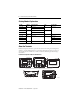
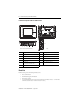
PanelView Component HMI Terminals Item Description Item Description 1 Function keys, keypad, or touch display 4 USB device port 2 24V DC power input 5 RS-232 serial port 3 RS-422 and RS-485 port 6 USB host 7 PanelView Component C400 Terminal 10 4 9 3 1 11 2 8 5 6 7 5 Item Description Item Description 1 Touch display, function keys 7 24V DC power input 2 Power status LED(1) 8 USB device port 3 RS-422 and RS-485 port 9 USB host port 4 RS-232 serial port 10 Replac
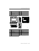
PanelView Component HMI Terminals PanelView Component C600 and C1000 Terminals 9 8 PanelView C600 FAULT 1 10 T T- R R- S B 6 1 11 2 3 4 5 6 7 (C600 Series C terminal shown) 44869 Item Description Item Description 1 Touch display 7 USB device port 2 24V DC power input 8 Diagnostic status indicator 3 10/100 MBit Ethernet port 9 Replaceable real-time clock battery 4 RS-422 or RS-485 port 10 USB host port 5 Mounting slots (for 2711C-T6M, -T6C Series C or later, 2711C-T6T S
PanelView Component HMI Terminals 9 Install the Terminal Before installing the terminal in a panel, review minimum clearances, panel guidelines, panel cutout dimensions, and product dimensions. Minimum Spacing Plan for adequate space around the terminal, inside the enclosure, for ventilation and cabling. Consider heat produced by other devices in the enclosure. The ambient temperature around the terminal must be 0…50 °C (32… 122 °F).
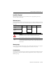
PanelView Component HMI Terminals Panel Cutout Dimensions Use the template shipped with your terminal to mark the cutout dimensions. PanelView Component Terminal Height, Approx., mm (in.) Width, Approx., mm (in.) C200 Function Key and C300 Touch 64.0 ± 1.0 (2.52 ± 0.04) 99.0 ± 1.0 (3.90 ±0.04) C200 and C300 Keypad C400 Touchscreen and function keys 99.0 ± 1.0 (3.90 ± 0.04) 119.0 ± 1.0 (4.69 ±0.04) C600 Touch 135.0 ± 1.0 (5.31 ± 0.04) 189.0 ± 1.0 (7.44 ±0.04) C1000 Touch 231.0 ± 1.0 (9.
PanelView Component HMI Terminals IMPORTANT 11 The terminal temperature must be greater than 0 °C (32 °F) during panel installation. 1. Push the terminal firmly into the cutout on all sides and corners until the plastic bezel contacts the enclosure and the gasket is fully compressed. Pan elVie Pane wC 600 lView C6 00 Pane lView C600 44870 You will hear a series of clicks as the clamps self-adjust to the panel thickness.
PanelView Component HMI Terminals These views show the panel clamps fully extended to secure the terminal against the rear of the panel. Fully extended panel clamps 6 1 44871 6 1 44872 ATTENTION: Follow the instructions to provide a proper seal and to prevent potential damage to the terminal. Allen-Bradley assumes no responsibility for water or chemical damage to the terminal or other equipment within the enclosure because of improper installation.
PanelView Component HMI Terminals 13 4. Rotate each lever in the direction indicated until it is in the final latch position. Rotate until the short, flat side of the lever aligns with an alignment mark on the terminal. 6 44907 Six alignment marks Use this table as a guide to provide an adequate gasket seal between the terminal and the panel. Typical Terminal Markings for Lever Panel Thickness Range Gauge Alignment Position 6 1 44908 1 1.52…2.01 mm (0.060…0.079 in.) 16 2 2.03…2.64 mm (0.08…0.
PanelView Component HMI Terminals 3. Push each panel clamp in until it is fully depressed and locked. Depressed and locked, the panel clamps provide adequate clearance to remove the terminal. 6 1 44873 4. Grip the sides of the bezel and gently pull the terminal out of the panel opening. 6 1 44874 Before reinstalling the terminal in the panel opening, you must release each panel clamp from its locked position. Do this as soon as possible after the removing the terminal from the panel.
PanelView Component HMI Terminals 15 Arrow icon 44875 Insert screwdriver here. Incorrect side of clamp Other incorrect locations for inserting the screwdriver 44876 The panel clamp will release and return to its unlocked position. 2. Reinstall the terminal in the panel after unlocking all the panel clamps. Mount the C400 or C1000 Terminal in a Panel Mounting levers secure the PanelView Component C1000 or C400 terminal to the panel.
PanelView Component HMI Terminals 1. Cut an opening in the panel using the template shipped with the terminal. 2. Make sure the sealing gasket is properly positioned on the terminal. This gasket forms a compression type seal. Do not use sealing compounds. 3. Place the terminal in the panel cutout. IMPORTANT The terminal temperature must be greater than 0 °C (32 °F) during panel installation. 4. Insert all mounting levers into the mounting slots on the terminal.
PanelView Component HMI Terminals 17 Follow the latching sequence for the optimum terminal fit. Rotate until notch in lever aligns with proper alignment mark on terminal. Notch 6 6 44880 Six alignment marks Latching sequence for the six levers: 1 4 6 5 3 2 Use this table as a guide to provide an adequate gasket seal between the terminal and the panel. Terminal Markings for Alignment 3 2 1 6 5 4 1 6 44881 Lever Position Panel Thickness Range Typical Gauge 1 1.52…2.01 mm (0.060…0.079 in.
PanelView Component HMI Terminals Product Dimensions PanelView Component C200 and C300 Keypad Terminals c d PanelView C300 a F1 1 F2 2 F3 3 F4 4 F5 5 F6 6 F7 7 F8 8 F9 9 F10 0 b 44882 PanelView Component C200 Function Key and C300 Touch Terminals c d PanelView C200 a F1 F2 F3 F4 b 44883 PanelView Component C200 and C300 Dimensions Height, Approx. Width, Approx. Overall Depth, Approx. Mounted Depth, Approx. a b c d PanelView Component C200 Keypad C300 Keypad 119 mm (4.69 in.
PanelView Component HMI Terminals 19 PanelView Component C400 Touch Terminals c d a b 45850 PanelView Component C600 Touch Terminals c d PanelView C600 a b 44884 Publication 2711C-IN001H-EN-P - July 2014
PanelView Component HMI Terminals PanelView Component C1000 Touch Terminals c d PanelView C1000 6 a 6 b 44885 PanelView Component C600, C1000, and C400 Dimensions Height, Approx. Width, Approx. Overall Depth, Approx. Mounted Depth, Approx. a b c d PanelView Component C400 Touch 113 mm (4.45 in.) 138 mm (5.43 in.) 43 mm (1.69 in.) 38 mm (1.49 in.) C600 Touch 154 mm (6.0 in.) 209 mm (8.23 in.) 57 mm (2.25 in.) 49 mm (1.93 in.) C1000 Touch 250 mm (9.84 in.) 308 mm (12.13 in.
PanelView Component HMI Terminals 21 WARNING: The USB port is intended for temporary local programming purposes only and not intended for permanent connection. If you connect or disconnect the USB cable with power applied to this module or any device on the USB network, an electrical arc can occur. This could cause an explosion in hazardous location installations. Be sure that power is removed or the area is nonhazardous before proceeding. ATTENTION: Do not use the USB port in hazardous locations.
PanelView Component HMI Terminals PanelView Component devices have been tested to operate with 2711P-RSACDIN and 1606-XLP power supplies. To use another power supply, review the criteria in the table. Power Supply Criteria If the PanelView Component HMI Use a Description Connects to equipment with isolated communication ports SELV or PELV power supply Other equipment can share this power supply with the PanelView Component device provided that no ground loops are created.
PanelView Component HMI Terminals 23 2. Gently pry the terminal block away from the terminal to release the locking mechanism. 44886 Follow these steps to replace the terminal block. 1. Press the terminal block base in first with the block leaning outward. 2. Gently push the top of the terminal block back to a vertical position to snap in the locking tab. Connect Power All PanelView Component devices connect to a 24V DC power source. The table shows the power ratings for each device.
PanelView Component HMI Terminals WARNING: Use supply wires suitable for 30 °C (86 °F) above surrounding ambient. WARNING: If you connect or disconnect wiring while the power is on, an electrical arc can occur. This could cause an explosion in hazardous location installations. Be sure that power is removed or the area is nonhazardous before proceeding. The input power terminal block supports these wire sizes.
PanelView Component HMI Terminals 25 4. Apply 24V DC power to the terminal. DC+ DC- Functional Earth Ground to Ground Bus 44887 Ground the Terminal PanelView Component devices have a functional earth terminal that you must connect to a low-impedance earth ground. The functional earth connection is on the power input terminal block. The negative power terminal is not internally connected to earth ground. ATTENTION: The functional earth connection to ground is mandatory.
PanelView Component HMI Terminals Cables for PanelView Component Terminals Cat. No. Description For Use With 1747-CP3 Serial 9-pin D-shell to 9-pin D-shell null modem cable C200, C300, C400, C600, C1000 1761-CBL-PM02 Serial 9-pin D-shell to 8-pin mini DIN cable, 2 m (6.
PanelView Component HMI Terminals 27 Interpret the LED Indicators at Startup The C400, C600 and C1000 terminals have indicators on the back of the unit to isolate operating problems. • Comm indicator for communications • Fault indicator for hardware faults At startup, the Fault indicator is off, except for a few brief flashes, and the Comm indicator is on. If the indicators remain off, check the power cable.
PanelView Component HMI Terminals WARNING: To avoid the danger of explosion, only replace the battery with 2711P-RY2032 or a manufacturer’s equivalent such as the Matsushita or Duracell DL2032. For safety information on the handling of lithium batteries, see the Guidelines for Handling Lithium Batteries, publication AG 5-4. Do not dispose of battery in a fire or incinerator. Dispose of used batteries in accordance with local regulations.
PanelView Component HMI Terminals 29 The battery is on the back of the terminals. No special tools are required to remove the battery cover and replace the battery. C600/C1000 Battery Battery Cover Battery This equipment is sensitive to electrostatic discharge (ESD) Follow ESD prevention guidelines when handling this equipment. 44888 Battery C400 Battery Battery Cover This equipment is sensitive to electrostatic discharge (ESD). Follow ESD prevention guidelines when handling this equipment.
PanelView Component HMI Terminals Backlight Disposal IMPORTANT The backlight assembly in the PanelView C600 (2711C-T6M, 2711C-T6C only) and C1000 devices contain mercury. At the end of its life, this equipment should be collected separately from unsorted municipal waste.
PanelView Component HMI Terminals 31 PanelView Component - 2711C-F2M, 2711C-K2M, 2711C-T3M, 2711C-K3M, 2711C-T6M, 2711C-T4T, 2711C-T6C, 2711C-T6T, 2711C-T10C Attribute Value C200 Power consumption, max C300 5W (0.21 A @ 24V DC) C400 C600 C1000 7W (0.28A @ 24V DC) 10 W (0.42 A @ 24V DC) 18 W (0.75 A @ 24V DC) Weight, approx. Function key: 0.19 kg (0.40 lb) Keypad: 0.30 kg (0.65 lb) Keypad: 0.30 kg (0.65 lb) Touch: 0.20 kg (0.43 lb) Touch: 0.347 kg (0.76 lb) Touch: 0.68 kg (1.48 lb) Touch: 1.
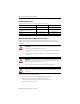
PanelView Component HMI Terminals Environmental Specifications Attribute Value Temperature, surrounding, max 50 °C (122 °F) Heat dissipation C200 and C300 C400 C600 C1000 16 BTU/hr 24 BTU/hr 32 BTU/hr 58 BTU/hr Relative humidity IEC 60068-2-30 (Test Db, Unpackaged Damp Heat): 5…95% noncondensing Vibration IEC 60068-2-6 (Test Fc, Operating): 2 g @ 10…500 Hz Shock, operating IEC 60068-2-27 (Test Ea, Unpackaged Shock): 15 g @ 11 ms Shock, nonoperating IEC 60068-2-27 (Test Ea, Unpackaged Shock
PanelView Component HMI Terminals 33 Certifications EAC Russian Customs Union TR CU 020/2011 EMC Technical Regulation RCM Australian Radiocommunications Act, compliant with: AS/NZS CISPR 11; Industrial Emissions KC Korean Registration of Broadcasting and Communications Equipment, compliant with: Article 58-2 of Radio Waves Act, Clause 3 (1) See the Product Certification link at http;//www.ab.com for Declarations of Conformity, Certificates, and other certification details.
PanelView Component HMI Terminals Notes: Publication 2711C-IN001H-EN-P - July 2014
PanelView Component HMI Terminals 35 Notes: Publication 2711C-IN001H-EN-P - July 2014
Rockwell Automation Support Rockwell Automation provides technical information on the Web to assist you in using its products. At http://www.rockwellautomation.com/support/, you can find technical manuals, a knowledge base of FAQs, technical and application notes, sample code and links to software service packs, and a MySupport feature that you can customize to make the best use of these tools.