Installation Instructions PanelView 550/600 Touch Screen Terminals Catalog Numbers 2711-T5AxxL1, 2711-T6CxxL1 Topic Page Important User Information 2 Hazardous Location Considerations 3 European Union Directive Compliance 4 Wiring and Safety Guidelines 5 Enclosures 5 Required Tools 6 Mounting Dimensions 6 Clearances 7 Cutout Dimensions 8 Installing Terminal in Panel 9 Installing the Memory Card Retainer 11 Connecting DC Power 12 EtherNet/IP Protocol 14 ControlNet Protocol 14
PanelView 550/600 Touch Screen Terminals Important User Information Solid state equipment has operational characteristics differing from those of electromechanical equipment. Safety Guidelines for the Application, Installation and Maintenance of Solid State Controls (Publication SGI-1.1 available from your local Rockwell Automation sales office or online at http://literature.rockwellautomation.
PanelView 550/600 Touch Screen Terminals 3 Hazardous Location Considerations This equipment is suitable for use in Class I, Division 2, Groups A, B, C, D; Class II, Division 2, Groups F, G; Class III, Division 2; or non-hazardous locations only. The following WARNING statement applies to use in hazardous locations. WARNING EXPLOSION HAZARD • Substitution of components may impair suitability for Class I, Class II, Class III Division 2.
PanelView 550/600 Touch Screen Terminals European Union Directive Compliance If a PanelView 550/600 touch screen terminal is installed within the European Union or EFTA regions and has a CE mark, the following regulations apply.
PanelView 550/600 Touch Screen Terminals 5 Wiring and Safety Guidelines Install the PanelView 550/600 touch screen terminal using publication 70E, Electrical Safety Requirements for Employee Workplaces. In addition to the NFPA general guidelines, follow these recommendations: • Route incoming power to the PanelView 550/600 terminal by a separate path from the communications cable. • Where power and communication lines must cross, they should cross at right angles.
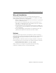
PanelView 550/600 Touch Screen Terminals Required Tools Other than the tools required to make the panel cutout, the tools required for installation are: • 7mm (M4) deep well socket wrench or nut driver. • small slotted screwdriver. • torque wrench (N•m, lb•in). Mounting Dimensions PV550 Touch Top View 152 mm (6.00 in.) 82 mm (3.20 in.) 64 mm (2.54 in.) 185 mm (7.28 in.) PV600 Touch Top View 152 mm (6.00 in.) 185 mm \(7.28 in.) Publication 2711-IN034F-EN-P - February 2009 79 mm (3.12 in.
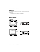
PanelView 550/600 Touch Screen Terminals 7 Clearances Allow adequate clearances for mounting, air flow, maintenance, and for installing a memory card. Side, Top and Bottom Clearances 25 mm (1 in.) for Mounting/Air Flow TERMINAL CUTOUT Use Full Size Template shipped with Terminal 25 mm (1 in.) for Mounting and Air Flow 38 mm (1.5 in.) for Mounting 25 mm (1 in.) for Mounting and Air Flow PV550 Back Clearance 64 mm (2.54 in.) Memory Card Retainer 109 mm (4.30 in.) 188 mm (7.4 in.
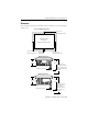
PanelView 550/600 Touch Screen Terminals Cutout Dimensions Use the full size template shipped with the PV550 or PV600 terminal to mark the cutout dimensions. The figure below shows a reduced size cutout. 165 mm (6.49 in) 4.8 mm dia. (0.188 in.) 98 mm (3.86 in.) Publication 2711-IN034F-EN-P - February 2009 158 mm (6.20 in) R 1.8 mm dia. (0.07 in.) 125 mm (4.91 in.
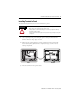
PanelView 550/600 Touch Screen Terminals 9 Installing Terminal in Panel To install the PV550/PV600 touch screen terminal in a panel: ATTENTION Disconnect all electrical power from the panel before making cutout. Make sure the area around the panel cutout is clear. Take precautions so that metal cuttings do not enter any components that may already be installed in panel. Failure to follow this warning may result in personal injury or damage to the panel components. 1.
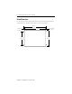
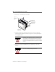
PanelView 550/600 Touch Screen Terminals 4. Install the 4 self-locking nuts, hand tight. Protective Installation Label Self-Locking Nuts (4 used, 8 provided) Mounting Studs (2 left/2 right) PV600 shown, PV550 similar 5. Alternately tighten the self-locking nuts until the terminal is held firmly against the panel. Tighten the nuts to a torque of 1.13 N•m (10 lb•in). Do not overtighten nuts. ATTENTION Mounting nuts must be tightened to a torque of 1.
PanelView 550/600 Touch Screen Terminals 11 Installing the Memory Card Retainer The memory card retainer is required for UL508 installations where a memory card is inserted in the card slot. The retainer protects against Electrostatic Discharge (ESD) up to 15KV and prevents accidental removal of a memory card in high vibration environments. To attach the memory card retainer: Retainer Base Memory Card Retainer Base Mounting Screws PV500 shown, PV600 similar 1.
PanelView 550/600 Touch Screen Terminals Connecting DC Power All of the PV550/600 touch screen terminals (e.g., Catalog No. 2711-T5A1L1 or 2711-T6C8L1) connect to a 24V DC power source. The table below shows the electrical ratings for the DC versions of the terminals. Electronic circuitry and an internal fuse protect the terminals from reverse polarity and over-voltage conditions. Terminal Type Supply Voltage Power Consumption PV550 Touch 18…2V DC, (24V DC nominal) 18 Watts max. (0.
PanelView 550/600 Touch Screen Terminals 13 To connect DC power to the PV550/PV600 touch screen terminal: 1. Secure the DC power wires to the terminal block screws. 2. Secure the Earth Ground wire to the correct terminal block screw. ATTENTION Explosion Hazard - Do not connect or disconnect equipment while circuit is live unless area is known to be non–hazardous. ATTENTION Do not apply power to the terminal until all wiring connections have been made. Failure to do so may result in electrical shock.
PanelView 550/600 Touch Screen Terminals EtherNet/IP Protocol The PanelView terminal is initially set to DHCP with BootP support (Dynamic Host Configuration Protocol) enabled. If your network has a DHCP/BootP server, you can connect the PanelView terminal to the EtherNet/IP network and the DHCP/BootP server will automatically establish an IP address. If your network does not have a DHCP/BootP server, you need to program an IP address.
PanelView 550/600 Touch Screen Terminals 15 Follow these steps to remove or replace the battery.
Rockwell Automation Support Rockwell Automation provides technical information on the Web to assist you in using its products. At http://support.rockwellautomation.com, you can find technical manuals, a knowledge base of FAQs, technical and application notes, sample code and links to software service packs, and a MySupport feature that you can customize to make the best use of these tools.