Installation Instructions PanelView 300 Keypad Terminals Catalog Number 2711-K3xxxxx Topic Page Important User Information 2 Hazardous Location Considerations 3 European Union Directive Compliance 3 Wiring and Safety Guidelines 4 Enclosures 5 Required Tools 5 Clearances 6 Installing Terminal in Panel 7 Installing the Memory Card Retainer 9 Connecting DC Power 10 Battery Removal and Disposal 11 For more information on the PanelView 300 Operator Terminals, refer to Publication 2711-U
PanelView 300 Keypad Terminals Important User Information Solid state equipment has operational characteristics differing from those of electromechanical equipment. Safety Guidelines for the Application, Installation and Maintenance of Solid State Controls (Publication SGI-1.1 available from your local Rockwell Automation sales office or online at http://literature.rockwellautomation.com) describes some important differences between solid state equipment and hard-wired electromechanical devices.
PanelView 300 Keypad Terminals 3 Hazardous Location Considerations This equipment is suitable for use in Class I, Division 2, Groups A, B, C, D; Class II, Division 2, Groups F and G; Class III Division 2; or non-hazardous locations only. The following WARNING statement applies to use in hazardous locations. WARNING EXPLOSION HAZARD • Substitution of components may impair suitability for Class I, Class II, Class III Division 2.
PanelView 300 Keypad Terminals EMC Directive This apparatus is tested to meet Council Directive 89/336/EEC Electromagnetic Compatibility (EMC) and amending directives 91/263/EEC, 92/31/EEC, 93/68/EEC using the following standards, in whole or in part: • EN 50081-2 EMC - Generic Emission Standard, Part 2 -Industrial Environment • EN 50082-2 EMC - Generic Immunity Standard, Part 2 - Industrial Environment(1) • EN 61000-6-2 EMC - Generic Immunity Standard, Part 2 - Industrial Environment(2) This product is
PanelView 300 Keypad Terminals 5 Enclosures Mount the PanelView 300 keypad terminal in a panel or enclosure to protect the internal circuitry. The terminal meets NEMA Type 12/13 and 4X (indoor use) ratings only when properly mounted in a panel or enclosure with the equivalent rating. Allow enough space within the enclosure for adequate ventilation. Consider heat produced by other devices in the enclosure. The ambient temperature around the PV300 terminal must be between 0…55 ° C (32…131 ° F).
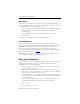
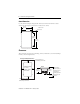
PanelView 300 Keypad Terminals Cutout Dimensions Use the full size template shipped with the PV300 terminal to mark the cutout dimensions. The figure below shows a reduced size cutout. 120 mm (4.71 in.) 109 mm R 4.5 mm dia. (0.178 in.) (4.29 in.) 140 mm (5.53 in.) 178 mm (6.99 in.) Clearances Allow adequate clearances for mounting, air flow, maintenance, and for installing a memory card and legend insert. Side, Top and Bottom Clearances Leave 64 mm (2.5 in.
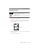
PanelView 300 Keypad Terminals 7 Installing Terminal in Panel To install the PV300 keypad terminal in a panel: ATTENTION Disconnect all electrical power from the panel before making cutout. Make sure the area around the panel cutout is clear. Take precautions so that metal cuttings do not enter any components that may already be installed in panel. Failure to follow this warning may result in personal injury or damage to the panel components. 1.
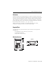
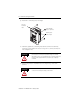
PanelView 300 Keypad Terminals 5. Install the 4 self-locking nuts, hand tight. Protective Installation Label Self-locking Nuts (4 used, 6 provided) Mounting Studs (2 left / 2 right) 6. Alternately tighten the self-locking nuts until the terminal is held firmly against the panel. Tighten the nuts to a torque of 1.13 N•m (10 lb•in). Do not overtighten nuts. ATTENTION Mounting nuts must be tightened to a torque of 1.
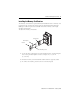
PanelView 300 Keypad Terminals 9 Installing the Memory Card Retainer The memory card retainer is required for UL508 installations where a memory card is inserted in the card slot. The retainer protects against Electrostatic Discharge (ESD) up to 15KV and prevents accidental removal of a memory card in high vibration environments. To attach the memory card retainer: Retainer Base Memory Card Retainer Base Mounting Screws 1.
PanelView 300 Keypad Terminals Connecting DC Power All of the PV300 terminals (Catalog No. 2711-K3AxxL1) connect to a 24V DC power source. The table below shows the electrical ratings for the DC versions of the terminals. Electronic circuitry and an internal fuse protect the terminals from reverse polarity and over-voltage conditions. Terminal Type Supply Voltage Power Consumption PV300 Keypad 18…32V DC, (24V DC nominal), Class 2 Power Supply 6 Watts (0.
PanelView 300 Keypad Terminals 11 2. Secure the Earth Ground wire to the correct terminal block screw. Explosion Hazard - Do not connect or disconnect equipment while circuit is live unless area is known to be non–hazardous. ATTENTION Do not apply power to the terminal until all wiring connections have been made. Failure to do so may result in electrical shock. 3. Apply 24V DC power to the terminal.
At the end of its life, the battery contained in this product should be collected separately from any unsorted municipal waste. Follow these steps to remove or replace the battery. 2 1 4 3 Series A Series B 5 6 7 8 PanelView, PanelView 300, Allen-Bradley, and Rockwell Automation are trademarks of Rockwell Automation, Inc. Trademarks not belonging to Rockwell Automation are property of their respective companies.