
Quick Start Manual User Manual

Publication 2711-QS003D-EN-P - June 2009 51
Creating the Application Chapter 3
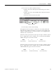
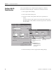
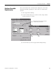
3. For each row, edit the attributes shown:
– Double-click in the Message Text field and type the alarm
message.
– Double-click in the Value/Bit (Bit offset) field and enter the
value shown.
– Click the check box in the Ack field.
4. Click OK to exit the Alarms dialog.
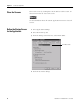
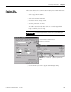
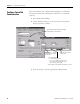
Bit triggered alarm messages are defined by a bit offset (Value/Bit
field) from the Trigger Tag address. For example, if the Trigger Tag
address is defined as B3:1/0, alarm messages can be triggered from
addresses B3:1/1 and B3:1/2.
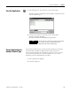
When the motor speed reaches 1200 rpm, the logic controller sets bit
B3:1/2, triggering an alarm condition. The message MOTOR SPEED
HIGH! will appear in the alarm banner.
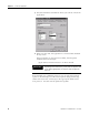
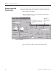
When the motor speed reaches 1500 rpm, the logic controller sets bit
B3:1/1, triggering an alarm condition. The message MOTOR SPEED
HIGH HIGH! will appear in the alarm banner.
Edit these fields.
B3:1/0
+
2=
Trigger Tag Address
Value/Bit of Alarm Message
B3:1/2
Logic Controller Address
B3:1/0
+
1=
Trigger Tag Address
Value/Bit of Alarm Message
B3:1/1
Logic Controller Address