User Guide Modbus Communications for PanelView Terminals Introduction 1 This document describes how to connect and configure communications for the Modbus versions of the PanelView terminals. This document provides supplemental information for the PanelBuilder32 manuals.
Modbus Communications for PanelView Terminals Related publications The following documentation provides additional information on installing, configuring and using your PanelView terminals. Publication Titles Number PanelBuilder32 Getting Results Manual 2711-6.19 PanelBuilder32 Quick Start Manual 2711-6.20 PanelView Operator Terminal Manual 2711-6.1 The Modicon website provides information and product descriptions of Modbus products at: www.modicon.
Modbus Communications for PanelView Terminals Modbus protocol 3 Modbus protocol links Modicon Programmable Controllers and devices emulating Modicon Programmable Controllers in a wide variety of applications. Modbus protocol defines a message structure that controllers can use regardless of the network type over which they communicate. Modbus is a half-duplex, master-slave communications protocol. The network master (PanelView) reads and writes coils and registers as if it was a Modicon controller.
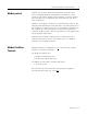
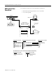
Modbus Communications for PanelView Terminals Typical Modbus Network Shown below is a typical Modbus network with Modbus Controllers installed on two of the network drops.
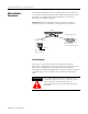
Modbus Communications for PanelView Terminals Connection to a Modbus Plus Network 5 Using a Bridge Multiplexer (BM85) or an RF modem, the Modbus PanelView can be connected to a Modbus Plus network. Modbus Plus is a local area network supporting up to 64 nodes at a data transfer rate of 1,000,000 bits/second. Modbus Plus provides host level peer-to-peer communication for network devices. The network also provides distributed input/output (DIO) communications.
Modbus Communications for PanelView Terminals Making Modbus Connections The PanelView Modbus protocol communicates with other devices over an RS-232 (point-to-point) or RS-485/RS-422 (multi-drop) serial link. Refer to the following pinout information to connect the PanelView to a Modbus network. Important: Follow the Modbus network layout and design as specified by the user manual for your programmable controller.
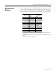
Modbus Communications for PanelView Terminals Connector Pinout Definitions 7 The communication type is downloaded with an application or is set on the terminal configuration screen. The PanelView supports RS-232, RS-485 and RS-422 communication standards. The Modbus 9-pin male D shell connector has the following pin definitions for each standard.
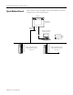
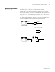
Modbus Communications for PanelView Terminals Making Serial Port Connections Use the RS-232 serial port on the PanelView terminal to: • download/upload applications over a serial link • or to connect a printer Computer PanelView COMM 1 or 2 RS-232 Printer/ File Transfer Port Available Cables 2711-NC13 5 m (16.4 ft) 2711-NC14 10 m (32.
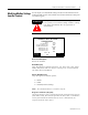
Modbus Communications for PanelView Terminals Modifying Modbus Settings from the Terminal 9 You can display or modify Modbus settings directly from the terminal. From the Configuration Mode menu of the terminal, select Serial Communication Setup. The screen below appears. ATTENTION ! Settings downloaded with a Modbus application have priority over terminal settings. Modbus settings take effect immediately after an application is downloaded.
Modbus Communications for PanelView Terminals Port/Modem Handshake [F5] Steps through the available options: • MODEM • RS-232 • RS-422 • RS-485 Note: The following delays (RTS TX, RTS Off, and CTS Timeout) facilitate modem communications. Refer to your modem user manual for information on the recommended delay values. RTS TX Delay (ms) [F6] Opens the numeric entry scratchpad. Provide a delay value of 0 to 2000 milliseconds.
Modbus Communications for PanelView Terminals Setting up Communications 11 Setting up Modbus communications for an application includes: • selecting a Modbus terminal when creating the application. • configuring communication parameters for the terminal on the Modbus link.
Modbus Communications for PanelView Terminals Configuring Modbus Communications Modbus communication parameters are accessed from the Terminal Setup dialog. To open the Terminal Setup dialog, choose Terminal Setup from the PanelBuilder32 Application menu. If RS232, RS422, or RS422 Port Configuration is selected If Modem Handshaking is selected 1. Click the Comms. Setup button from the Terminal Setup dialog. 2. Under Network Devices, edit the following parameters: Publication 2711-6.
Modbus Communications for PanelView Terminals 13 3. Under Terminal, edit the following parameters: Specify: To: Slave Response Timeout (msec) Enter a value between 20 and 5000 milliseconds. The default is 250. This timeout specifies the time, after a command is sent by the PanelView terminal, that an error is indicated by no response from the slave device. Baud Rate Select the baud rate of the Modbus link.
Modbus Communications for PanelView Terminals Modbus Address Spaces The PanelView reads and writes data into other Modbus devices on the same network. The Node Address specifies the device (node) and the Address Type specifies the address space.
Modbus Communications for PanelView Terminals 15 Data and Address Types Not all of the data types are compatible with every address type. The following table shows the Address Type available based on the selected data type.
Modbus Communications for PanelView Terminals Data Format Modicon controllers communicate in either ASCII or RTU (Remote Terminal Unit) transmission mode. The PanelView only supports RTU mode. In RTU mode, each 8-bit byte contains 2 four-bit hexadecimal characters.
Modbus Communications for PanelView Terminals 17 Tag Editor Fields Field Description Valid Characters Notes Tag Name Name of tag. Maximum characters = 32 A-Z, a-z, 0-9 hyphen (-), underscore (_), percent (%) - Tag name must be unique. - Can’t start with 0-9, hyphen, or percent - Tag names are not case sensitive. - Do not use blanks, tabs, carriage returns or non-printable characters. Data Type Data format of tag.
Modbus Communications for PanelView Terminals Field Description Valid Characters Notes Type Determines address of the data in the slave device. Options are: Input Status Output Coil Input Register Holding Register Address Type may support some or all of the data types. Refer to page 15. Scaling Scale: ‘m’ in y = mx + b Offset: ‘b’ in y = mx + b Values you want to use to convert the current tag’s processor integer value (‘x’) to engineering units (‘y’).
Modbus Communications for PanelView Terminals Downloading Applications over a Serial Link 19 To download a Modbus application from your computer to the PanelView terminal over an RS-232 link: • connect computer to RS-232 port of PanelView terminal • download application from the PanelBuilder32 File menu Downloading Application using the Internal DF1 Driver This section shows how to download an application from a serial COM port on your computer to the RS-232/DF1 port of the PanelView terminal using a p
Modbus Communications for PanelView Terminals Modbus Application Report The application printout for Modbus provides the following information: • configuration data • tag data Error Messages and Codes The following tables lists error messages and codes specific to Modbus communications. For all other messages, refer to the PanelView Operator Interface manual or the PanelBuilder32 online help.
Modbus Communications for PanelView Terminals 21 The following errors are not specific to Modbus but may appear when you exit the Tag Editor. Message Recommended Action Minimum Value is invalid, must be between 0 and 9999 Enter appropriate value in Tag Editor. Minimum Value is invalid, must be between 0 and 65535 Enter appropriate value in Tag Editor. Minimum Value is invalid, must be between –32768 and 32767 Enter appropriate value in Tag Editor.
Modbus Communications for PanelView Terminals Message Recommended Action Not enough network node address space to support a tag of this data type. Change the tag address to reference a lower numbered discrete address or register. Not enough RAM on Daughtercard to support the size of this user application file. Group tag addresses together as much as possible, otherwise remove screen objects. Translation Failure Contact Allen-Bradley for technical support. Publication 2711-6.
Modbus Communications for PanelView Terminals 23 Communication Status Error Messages These errors appear as a banner at the top of an application screen (error #634 in upper left corner) or as a status display on the terminal configuration screen. Note: Since the PanelView is configured as a master device, communication status is not updated until the PanelView requests information. If communications are lost, the PanelView displays the last communication status.
Glossary Coil Bit location in a a Modbus device. Digital Tag A bit address. Inputs Data which is received by the logic controller from other devices. Master Device which sends messages (queries) to one or more slave devices. Modicon Controller Refers to the 184/384, 484, 584, 884, M84 (micro), or 984 family of Modicon logic controllers. Outputs Data which is sent by a logic controller to other devices. Register 16 bit unsigned value residing in a Modbus device.