PanelViewt1200 Operator Terminals (Catalog Numbers 2711-KA1, KC1, TA1, TC1, TA4, TC4) User Manual
Important User Information Solid-state equipment has operational characteristics differing from those of electromechanical equipment. “Safety Guidelines for the Application, Installation and Maintenance of Solid State Controls” (Publication SGI–1.1) describes some important differences between solid-state equipment and hard-wired electromechanical devices.
Table of Contents Preface . . . . . . . . . . . . . . . . . . . . . . . . . . . . . . . . . . . . . . . P 1 Manual Overview . . . . . . . . . . . . . . . . . . . . . . . . . . . . . . . . . . . . Intended Audience . . . . . . . . . . . . . . . . . . . . . . . . . . . . . . . . . . . Glossary of Terms . . . . . . . . . . . . . . . . . . . . . . . . . . . . . . . . . . . Related Publications . . . . . . . . . . . . . . . . . . . . . . . . . . . . . . . . . . After Sales Support . . . . . . . . . . . . . .
ii Table of Contents Information and Alarm Windows . . . . . . . . . . . . . . . . . . . . . . . . . Summary of PLC Controlled Options . . . . . . . . . . . . . . . . . . . . . . Applicable Programmable Controllers and Connections . . . . . . . . . PLC 5/11, 5/15, 5/20, 5/25, 5/30, 5/40, 5/60 and 5/250 Processors PLC 5/10 Processor . . . . . . . . . . . . . . . . . . . . . . . . . . . . . . . . PLC 3 and PLC 3/10 Processors . . . . . . . . . . . . . . . . . . . . . . .
Table of Contents iii Battery Failure . . . . . . . . . . . . . . . . . . . . . . . . . . . . . . . . . . . . PanelView 1200 Terminal Printing . . . . . . . . . . . . . . . . . . . . . . . . Print Priorities . . . . . . . . . . . . . . . . . . . . . . . . . . . . . . . . . . . . Page Formatting . . . . . . . . . . . . . . . . . . . . . . . . . . . . . . . . . . Non Printable Characters . . . . . . . . . . . . . . . . . . . . . . . . . . . . Printer Errors . . . . . . . . . . . . . . . . . . . . . . . . .
iv Table of Contents Specifications . . . . . . . . . . . . . . . . . . . . . . . . . . . . . . . . . . A 1 Design Certifications, Standards and Compliances . . . . . . . . . . . . Design Standards Complied With . . . . . . . . . . . . . . . . . . . . . . Terminal Weights . . . . . . . . . . . . . . . . . . . . . . . . . . . . . . . . . . . . Keypad Terminals . . . . . . . . . . . . . . . . . . . . . . . . . . . . . . . . . Front Panel Design . . . . . . . . . . . . . . . . . . . . . . . . . . . . . . .
Preface Preface Manual Overview This manual describes the features and specifications of PanelView1200 terminals. PanelView 1200 terminals are available as keypad or touch screen terminals, with color or monochrome display. Note The term “PanelView 1200” is the new name for PanelView terminals. It refers to all 12-inch CRT PanelView terminals, from Series A upwards.
Preface Hex Files: Application files which have been converted into Intel Hex format for transfer to user PROMs. Object: An object is an individual component of a PanelView 1200 screen. Each object takes the function of a button, switch or indicator on a control panel. The objects can be dynamic—they can change color or value and can display information. Each object is defined by the developer of the PanelView 1200 screen.
Preface There are two types of user PROM chips that can be used in PanelView 1200 terminal: EPROMs and EEPROMs. EPROMs are Electrically Programmable Read Only Memory chips. EEPROMs are Electrically Erasable Programmable Read Only Memory chips. The user PROMs store application files in memory that is protected from power failure and failure of the internal battery. A PROM burner is required to copy application files into a user EPROM.
Preface To identify the manuals referring to these programmable controllers, consult the Publications Index, Publication SD499, available from Allen-Bradley. After Sales Support If you need help with your PanelView 1200 terminal, contact: Allen-Bradley Global Technical Support 6680 Beta Drive Mayfield Village, Ohio 44143 Inside USA and Canada: 1-800-289-2279 Outside USA and Canada, contact your local Allen-Bradley office or call USA (216) 646-6800.
Chapter 1 Introduction to PanelView 1200 Operator Terminals This chapter provides an overview of the PanelView 1200 terminals. It describes: the types and features of PanelView 1200 terminals the available options and accessories the supported Allen-Bradley programmable controllers and remote I/O scanners The PanelView 1200 Terminal Family PanelView 1200 terminals provide a fast, easy, flexible and low cost operator interface for a PLC system. They are ideal replacements for traditional control panels.
Chapter 1 Introduction to PanelView 1200 Operator Terminals ÁÁÁÁÁÁÁÁÁÁ ÁÁÁÁÁÁÁÁÁ ÁÁÁÁÁ ÁÁÁÁÁÁÁÁÁÁ ÁÁÁÁÁÁÁÁÁÁÁÁÁÁ ÁÁÁÁÁ ÁÁÁÁÁÁÁÁÁÁ ÁÁÁÁÁÁÁÁÁÁ ÁÁÁÁÁÁÁÁÁÁ ÁÁÁÁÁÁÁÁÁÁ ÁÁÁÁÁ ÁÁÁÁÁ ÁÁÁÁÁÁÁÁÁÁ ÁÁÁÁÁÁÁÁÁÁ ÁÁÁÁÁÁÁÁÁÁÁÁÁÁ ÁÁÁÁÁÁÁÁÁÁ ÁÁÁÁÁÁÁÁÁÁ ÁÁÁÁÁ ÁÁÁÁÁÁÁÁÁÁ ÁÁÁÁÁÁÁÁÁÁ ÁÁÁÁÁ ÁÁÁÁÁÁÁÁÁÁ ÁÁÁÁÁÁÁÁÁÁ ÁÁÁÁÁÁÁÁÁÁÁÁÁÁ ÁÁÁÁÁÁÁÁÁÁ ÁÁÁÁÁÁÁÁÁÁ ÁÁÁÁÁ ÁÁÁÁÁÁÁÁÁÁ ÁÁÁÁÁÁÁÁÁÁ ÁÁÁÁÁÁÁÁÁÁÁÁÁÁ ÁÁÁÁÁÁÁÁÁÁ ÁÁÁÁÁÁÁÁÁÁ ÁÁÁÁÁ ÁÁÁÁÁÁÁÁÁÁ ÁÁÁÁÁÁÁÁÁÁ ÁÁÁÁÁÁÁÁÁÁÁÁÁÁ ÁÁÁÁÁÁÁÁÁÁ ÁÁÁÁÁÁÁÁÁÁ ÁÁÁÁÁÁÁÁÁÁ ÁÁÁÁÁÁÁÁÁ ÁÁÁÁÁ ÁÁÁÁÁ ÁÁÁÁÁÁÁÁÁÁ ÁÁÁÁÁÁÁÁÁÁ
Chapter 1 Introduction to PanelView 1200 Operator Terminals Table 1.
Chapter 1 Introduction to PanelView 1200 Operator Terminals 12" Monochrome or Color Display All PanelView 1200 terminals have a 12” display in monochrome (amber) or color. Color terminals can display 8 colors at a time from a choice of 16. Direct Connection to any Allen Bradley PLC Remote I/O Link You can integrate a PanelView 1200 terminal quickly and easily into any PLC system capable of supporting the Allen-Bradley 1771 Remote I/O Link.
Chapter 1 Introduction to PanelView 1200 Operator Terminals User Definable Keys The keypad terminal has 21 user-definable keys on its front panel. Each one can perform a variety of operations—from turning on PLC input bits to changing screens. PanelView 1200 terminals are extremely flexible: each key can be assigned a different function for each screen. Custom Keypad Legend Inserts The function keys on keypad terminals are pre-labeled at the factory, but you can create key labels to suit your application.
Chapter 1 Introduction to PanelView 1200 Operator Terminals Built in Clock The battery-backed clock runs even when the terminal is powered down. PanelView 1200 can display the current time and date and can send it to the PLC controller. The clock may also be set by the PLC controller.
Chapter 1 Introduction to PanelView 1200 Operator Terminals PanelView 1200 Terminal Diagnostics When a PanelView 1200 terminal starts up, it performs a number of fault detection tests. The PanelView 1200 terminal also performs continuous tests for fault conditions when it is communicating online with the PLC controller. In the event of a fault, a message appears, pinpointing the exact nature of the fault. An operator can also initiate diagnostic tests from the terminal.
Chapter 1 Introduction to PanelView 1200 Operator Terminals an EPROM can be used for application file back-up. The application file is programmed into the EPROM with a PROM burner. Once programmed, it cannot be erased or overwritten.
Chapter 1 Introduction to PanelView 1200 Operator Terminals You can also configure the terminal to beep when a key is pressed. Figure 1.
Chapter 1 Introduction to PanelView 1200 Operator Terminals Special Keys There are a series of special keys on the keypad terminal: the arrow keys are used with the Set Bit and Numeric Cursor Points and the ASCII Input object Home, Select work with the Set Bit and Numeric Input Cursor Points Cancel is designed to be used with all numeric keypads, Numeric Input and Set Bit Cursor Points. Raise and Lower are used with Numeric Input Cursor Points only.
Chapter 1 Introduction to PanelView 1200 Operator Terminals The touch screen terminal contains 120 touch cells. Each touch cell is 2 characters high by 8 characters wide. You can configure the terminal to beep when a touch cell is pressed. 16 characters fit in one touch cell 20002 Touch cells are grouped to create different types and sizes of buttons. The following figure illustrates a single touch cell ON button with double height and double width characters, and a solid border.
Chapter 1 Introduction to PanelView 1200 Operator Terminals Table 1.
Chapter 1 Introduction to PanelView 1200 Operator Terminals Objects Common to All PanelView 1200 Terminals The following objects can be displayed on both the keypad terminal and the touch screen terminal: Momentary Push Button (Normally Open) turns on (sets to 1) a PLC input control bit, as long as the button is held. Momentary Push Button (Normally Closed) resets a PLC input control bit that is normally set to 1. This bit stays off as long as the button is pressed.
Chapter 1 Introduction to PanelView 1200 Operator Terminals List Indicator displays a list of PLC states and highlights the current state. The value of the PLC address determines the item that will be highlighted in the list. Set Value Button transfers a pre-defined value to the PLC controller via the assigned PLC input address. Increment Value Button increases the value stored at a PLC input address each time the button is pushed.
Chapter 1 Introduction to PanelView 1200 Operator Terminals Screen Print Button allows an operator to print any screen currently displayed on the PanelView 1200 terminal. Local Message Display can be defined as a rectangular area of any size, and placed in any location on the PanelView 1200 terminal screen. A PLC control address is assigned to the object, allowing the PLC controller to trigger any one of up to 875 messages to appear in this area.
Chapter 1 Introduction to PanelView 1200 Operator Terminals Set Bit Cursor Point consists of a bit and a cursor character. This object is used to “point” to a screen character. Several set bit cursor points can be in the same screen. Each one can have a different (user-defined) pointer; only the current pointer is visible and blinking. The current cursor point’s input bit is always on, so the PLC controller always “knows” the current selection.
Chapter 1 Introduction to PanelView 1200 Operator Terminals Summary of PLC Controlled Options The following options can be controlled by the PLC controller: PLC Controlled Audio allows the PLC controller to control the PanelView 1200 terminal’s audio beeper. A PLC bit address is assigned. When the PLC controller sets this bit, the terminal’s beeper is activated. This does not interfere with the Alarm Window’s use of the beeper.
Chapter 1 Introduction to PanelView 1200 Operator Terminals The PanelView 1200 terminal appears as one or more I/O rack(s) to a PLC controller. It has the same configurability—and more—as a standard I/O rack. Refer to your applicable Allen-Bradley Programmable Controller and Remote I/O Scanner user’s manuals for various connection and remote I/O configuration limitations.
Chapter 1 Introduction to PanelView 1200 Operator Terminals SLC 5/02 via 1747 SN One or more PanelView 1200 terminals can be connected to the 1747-SN I/O Subscanner Module (SLC–5/02 RIO connection) for the SLC–5/02 processor. Each module provides an additional remote I/O link for the host programmable controller. The rack range of the 1747-SN is 0 to 3. Important No block transfers are possible with the SLC-5/02 and 1747-SN Series A module.
Chapter 2 PanelView 1200 Terminal Functions This chapter describes how to use the PanelView 1200 terminal’s two operating modes and discusses the power-up and on-line tests that the terminal performs. The PanelView 1200 terminal has two modes of operation: Configure mode and Run mode. Configure mode allows you to set up the terminal, and Run mode executes the application file.
Chapter 2 PanelView 1200 Terminal Functions With the optional Remote Keyswitch Assembly, you can access the Mode Select Keyswitch and RS-232 port from the front of the rack where the PanelView 1200 terminal is mounted. For more information on the Remote Keyswitch Assembly, see the instruction sheet supplied with that option. Fault Conditions There are two types of faults: major faults and minor faults.
Chapter 2 PanelView 1200 Terminal Functions Clear 20318 The operator must press the Clear button to resume normal operation. The Clear button temporarily overrides the function that was previously assigned to the associated function key or touch cells. Minor faults do not affect PLC communications. Power Up Functions When you power up the PanelView 1200 terminal, it performs a number of tests for major or minor faults to determine if any problems will affect its operation.
Chapter 2 PanelView 1200 Terminal Functions Important If the optional user EPROM or EEPROM is corrupted or not installed, the terminal will display this fault message each time it is powered up: Clear 20200 You can safely clear this message and continue. You can also disable this message altogether, through the Configuration Mode Menu item User EPROM/EEPROM Power-up Test, explained later in this chapter. In the case of a corrupted application file, download the file again.
Chapter 2 PanelView 1200 Terminal Functions Communication Test The PLC Communication test verifies that the communication card is installed and functioning. If the test fails, the following message is displayed in the status window at the top of the screen: PLC communication lost 20314 When this occurs, the status window will continue to flash on and off until the problem with the PLC controller is corrected.
Chapter 2 PanelView 1200 Terminal Functions The Configuration Mode Menu With the Mode Select Keyswitch set to Configure mode, the terminal displays the Configuration Mode Menu.
Chapter 2 PanelView 1200 Terminal Functions Important Downloading via the Pass-Through feature requires configuration in PanelBuilder software or “Manual” configuration in the terminal’s Pass-Through Download Options menu, so that the network information and the PanelView 1200 terminal’s location on the network is correct.
Chapter 2 PanelView 1200 Terminal Functions Important The Auto Line Feed and Auto Form Feed parameters are not used for uploading/downloading, and cannot be changed. Although you can choose 7 or 8 for the “Data Bits” option, always use 8 (the default), or you won’t be able to transfer. The 7 data bits option applies only to printer settings. You should not have to change the default settings for Upload/Download; the PanelBuilder software expects these settings.
Chapter 2 PanelView 1200 Terminal Functions Access Codes Choose Access Codes to assign up to eight security code settings. Once security codes are set, an operator will have to sign on using the appropriate code, in order to view screens that have assigned security. Screen security is assigned using PanelBuilder software. Important If a screen is triggered by the PLC Controlled Screen option, or if it is the Power-up screen, that screen will be displayed and no access code will be requested.
Chapter 2 PanelView 1200 Terminal Functions Audio Response The PanelView 1200 terminal can sound a beep whenever you press an active touch cell or keypad. The PLC controller can also trigger this audio indicator either directly with the PLC Controlled Audio, or through an alarm message. The button, alarm and volume parameters can be configured from the Audio Response screen.
Chapter 2 PanelView 1200 Terminal Functions Attention If you upload an application file from a PanelView 1200 terminal, the file will contain input states or values based on the last use of the terminal—not necessarily the terminal’s original preset values. If you want the file to contain the presets, press the Load Presets button before uploading. This resets the terminal’s retentive input functions as well. The following illustration shows the Preset Operations screen for a touch screen terminal.
Chapter 2 PanelView 1200 Terminal Functions Time and Date Choose Time and Date to set the PanelView 1200 terminal’s battery-operated clock.
Chapter 2 PanelView 1200 Terminal Functions Touching the screen or keypad causes the current screen to reappear. Mode changes, PLC generated Alarm Messages, Information Messages, PLC generated screen requests, or terminal fault messages also turn off the screen saver. Screen Alignment Choose Screen Alignment to set the position of the image on the terminal display. On a keypad terminal, use the function keys to change the alignment of a screen.
Chapter 2 PanelView 1200 Terminal Functions Pressing the Center Screen button sets the screen alignment to its default position. Pressing the Save & Exit button saves the current alignment and returns you to the Configuration Mode Menu. The following figure shows the Screen Alignment screen for a touch screen terminal.
Chapter 2 PanelView 1200 Terminal Functions The test starts running as soon as the screen is displayed; the number of false depressions and the last cell detected are reset to zero. The following illustration shows the False Depression Test screen. FALSE DEPRESSION TEST False Depressions : Last Cell Detected : Exit 20226 User EPROM/EEPROM Power Up Test PanelView 1200 terminals include a socket for an optional user PROM.
Chapter 2 PanelView 1200 Terminal Functions If you will not be installing the optional user PROM, this message serves no purpose. Disable it by choosing User EPROM/EEPROM Power-up Test from the Configuration menu, shown in the following illustration.
Chapter 2 PanelView 1200 Terminal Functions Choose No to tell the terminal to bypass the User EPROM/EEPROM test at power-up. The following message will appear: WARNING: Choose Yes" if EPROM/EEPROMS are installed Clear F8 23627 If you install a user PROM later, be sure to reset the power-up test to Yes. Pass Through Download Options The terminal Pass-Through Download Options allow you to configure the pass-through address manually from the terminal.
Chapter 2 PanelView 1200 Terminal Functions PASS-THROUGH DOWNLOAD OPTIONS >Auto Restart >Address Source >PLC Type >Baud Rate >Rack Number >Starting Module >Rack Size >Last Chassis >Module Group >High/Low Byte Manual Address Source Block Transfer Yes Application PLC 5/250 230.4K 77 0 Full Yes 7 High Up Cursor Down Cursor Change Data Choosing Manual Address Source will disable the Terminal's current application file. Select Application to enable.
Chapter 2 PanelView 1200 Terminal Functions Address Source You can choose between Application and Manual for the Address Source. The first time that you enter this screen, the default is Application. When you re-enter the screen, the values that were previously saved appear. When you set the Address Source to Manual, you invalidate the application file. When you set the Address Source back to Application, you revalidate the application file. It will execute normally.
Chapter 2 PanelView 1200 Terminal Functions If you toggle the Address Source to Manual but the current application file has no Pass-Through configuration and a manual address has not been configured and saved previously, the asterisks will be replaced by the following defaults: PLC Type: PLC-5/25 Baud Rate: 57.
Chapter 2 PanelView 1200 Terminal Functions Unit Tests Choose Unit Test to check the operation of various components of a PanelView 1200 terminal. The following illustration shows the Unit Tests screen for a touch screen terminal.
Chapter 2 PanelView 1200 Terminal Functions Important If the User PROM is not installed, the test will indicate a failure at memory location 5000:0000 for Series C and earlier terminals, or at 4000:0000 for Series D and E terminals. This is normal. Touch Panel (touch screen only) identifies touch cells that are difficult to activate or inoperable. During this test, the display shows 119 touch cells, in reverse video each with a distinct border on the inside of the cell.
Chapter 2 PanelView 1200 Terminal Functions The following illustration shows a Function Key Test screen. FUNCTION KEY TEST Exit 20207 Display tests the terminal’s display functions. The terminal shows samples of the different character sizes and attributes, as well as the terminal’s character set. Run Mode Functions Before switching to Run mode, make sure you’ve downloaded an application file, installed a user PROM containing one, or set the Pass-Through Download address source to Manual.
Chapter 2 PanelView 1200 Terminal Functions On line Diagnostic Testing The PanelView 1200 terminal performs periodic fault detection tests while on-line with the PLC controller. PLC Communication Timeout If communication between the PLC controller and PanelView 1200 terminal is interrupted, a special, flashing PLC Communication Lost status window appears on the top line of the display. The terminal will continue to operate, and operator-selected screens can be displayed.
Chapter 2 PanelView 1200 Terminal Functions Important Not all graphic characters will appear in screen prints. See Non-Printable Characters, on page 2-26, for more details. For details, see your PanelBuilder Development Software User Manual, or your PanelBuilder1200 Configuration Software for Windows User Manual. Print Priorities If you try to print more than one report, screen, or alarm message at a time, the terminal will print in order of priority, saving the other print jobs in a queue.
Chapter 2 PanelView 1200 Terminal Functions Non Printable Characters If you are printing screens, some graphic characters will not be printed.
Chapter 3 Installing Your PanelView 1200 Terminal This chapter describes how to install a PanelView 1200 terminal in your plant.
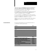
Chapter 3 Installing Your PanelView Terminal 1200 Terminal The PanelView 1200 Terminal The following figure shows the rear panels of the PanelView 1200 terminals. Note the location of the RS-232 port, the Alarm Relay connector, the Remote I/O connector, and the power connector. Figure 1.1 PanelView 1200 Terminal Rear Panels Contrast Control Fuses Fuses Power and Alarm Relay Terminal Blocks Power and Alarm Relay Terminal Blocks ........ ...... RS-232 Port Mode Select Keyswitch Remote I/O Connector ..
Chapter 3 Installing Your PanelView 1200 Terminal Figure 1.2 RS 232 Port RTS (5) DTR (6) Common (7) DCD (8) CTS (4) TXD (3) RXD (2) SHIELD (1) Pin 1 Pin 14 DSR(20) RS 232 SERIAL INTERFACE 20157 The Alarm Relay Connector The PanelView 1200 terminal can be used to trigger a remote alarm or warning light under specific conditions. You would attach this remote alarm or light to the Alarm Relay (as shown in the following figure). Figure 1.
Chapter 3 Installing Your PanelView Terminal 1200 Terminal The Remote I/O Connector The Remote I/O connector at the back of the PanelView 1200 terminal connects the terminal to the host PLC controller via the Remote I/O link, as shown in the following figure. If the PanelView 1200 terminal is the last device on the link, connect a 1/2 watt terminating resistor across pins 1 and 2. The value of the resistor depends on the Remote I/O baud rate: for 57.6 kilobaud and 115.
Chapter 3 Installing Your PanelView 1200 Terminal Figure 1.5 AC Power Connector L L1 N L2 GND 20164 Installing a User PROM The PanelView 1200 terminal is designed so that you can install an optional user PROM. With an EPROM chip, you must download your application file through a PROM burner. With an EEPROM used for application backup (not as extra application memory), the application file is automatically copied to the EEPROM when it is downloaded into the terminal.
Chapter 3 Installing Your PanelView Terminal 1200 Terminal Attention The electronic components in the PanelView 1200 terminal are extremely sensitive to static electricity and may be permanently damaged by electrostatic discharges.
Chapter 3 Installing Your PanelView 1200 Terminal Figure 1.7 Series E Logic Board with Jumpers JP1 and JP2 in the EPROM/EEPROM Position SYSTEM MEMORY Node Adapter Firmware System Firmware User PROM USER MEMORY JP2 JP1 U2 20319 7 Gently ease the chip’s pins into the socket. Attention The notch on the chip MUST be on the same end as the notch on the socket. Important Series C and earlier PanelView 1200 terminals use two PROMs as user memory.
Chapter 3 Installing Your PanelView Terminal 1200 Terminal There should be four unused holes visible to the right. The notch on the chip must still be on the right end, the same as the notch on the socket, as shown in the following figure. Figure 1.8 28 pin EPROM correctly positioned in a 32 pin Socket 23624 8 When all the pins are properly positioned in their holes, and the notch is on the correct side, gently press the chip into the socket. It will go in easily if the pins are properly positioned.
Chapter 3 Installing Your PanelView 1200 Terminal make sure that the notch on the chip is on the same end as the notch on its socket if a PROM burner was used, make sure that the instructions were correctly followed if an EEPROM was used, try downloading an application file to the terminal PanelView 1200 Terminal Dimensions The following diagrams show the dimensions of the keypad and touch screen terminals. Refer to these diagrams when mounting your terminal. Figure 1.
Chapter 3 Installing Your PanelView Terminal 1200 Terminal Figure 1.10 Color Keypad Terminal Dimensions Color Keypad PanelView F17 F18 F19 F20 F21 7 4 1 • 8 5 2 0 A A 9 6 3 - Y A HOME 13.97" (354.84 mm) 12.40" (314.96 mm) " B F1 F2 F3 F4 F5 F6 F7 F8 F9 F10 F11 F12 F13 F14 F15 F16 Raise SELECT Lower CANCEL 0.585" (14.86 mm) 19.00" (482.6 mm) 0.250" (6.350 mm) 0.400" (10.16 mm) 15.075" (382.91 mm) 21168 Figure 1.
Chapter 3 Installing Your PanelView 1200 Terminal Figure 1.12 Color Touch Screen Terminal Dimensions Color Touch Screen 13.50" (342.90 mm) 12.40" (314.96 mm) PanelView 13.80" (350.52 mm) 0.520" (13.21 mm) 0.680" 0.400" (17.27 mm) (10 .16 mm) 15.305" (388.75 mm) PanelView 1200 Terminal Cutouts 21191 Installation Notes PanelView 1200 terminals are installed in a rectangular cut-out in a panel. Depending on the model, the terminals mount with mounting studs or mounting clips.
Chapter 3 Installing Your PanelView Terminal 1200 Terminal Keypad Terminals (2711 KA1, 2711 KC1) The first diagram shows the keypad terminal panel cutout. The second diagram shows the modification to T30 panel cutout for keypad terminals. Figure 1.13 Keypad Terminal Panel Cutout CL 16.90" (429.26mm) CL 1.50" (38.1mm) CL CL 12.85" (326.39mm) 9.16" (232.66mm) 5.50" (139.70mm) 5.50" CUTOUT 8.70" (220.98mm) 6.70" (170.18mm) 1.50" 4.35" (110.49mm) 3-12 7/32" (5.56mm) DIA. TYP.
Chapter 3 Installing Your PanelView 1200 Terminal Figure 1.14 Modification to T30 Panel Cutout for Keypad Terminals 7/32" (5.56mm) DIA. TYP. 18 PLACES MOUNTING STUDS ARE #10-32 SIZE 1.08" (27.43mm) CUTOUT 6.425" (163.2mm) 16.90" (429.26mm) CL 12.85" (326.39mm) 6.425" 1.50" (38.1mm) 6.70" (170.18mm) 5.50" (139.70mm) 1.50" CL CUTOUT 5.50" 6.70" CUTOUT 1.08" 4.35" (110.49mm) 4.35" 8.70" (220.98mm) 8.70" 9.16" (232.66mm) 9.
Chapter 3 Installing Your PanelView Terminal 1200 Terminal Figure 1.16 Touch Screen Clip Mount Touch Screen Terminal Right Side of Chassis Screw Driver Slot Mounting Bracket Mounting Slot Upper Right Side Touch Screen Terminal Front Bezel 20313 Touch Screen Terminals (2711 TA4, TC4) Figure 1.17 Stud Mount Touch Screen Terminal Panel Cutout 13.11" (333 mm) 13.00" (330.2 mm) 7/32" (5.56 mm) DIA. TYP. 12 PLACES MOUNTING STUDS ARE #10-32 SIZE 4.30" (109.22 mm) CL 12.69" (322.33 mm) 6.24" (158.
Chapter 3 Installing Your PanelView 1200 Terminal Optional Clip or Stud Rack Mount Kits You can mount your PanelView 1200 touch screen terminal in a standard 19” rack. For TC1 and TA1 (clip-mount) terminals, use the optional NR1 Rack Mount Kit, and for TC4 and TA4 (stud-mount) terminals, use the optional NR2 Rack Mount Kit. Figure 1.18 NR1 19" Rack Mount Assembly for TC1 and TA1 Terminals Clip mount .578" (14.68 mm) .735" (18.67 mm) .278" (7.06 mm) .125" (3.18 mm) 1.48" (37.6 mm) 5.48" (139.
Chapter 3 Installing Your PanelView Terminal 1200 Terminal Remote Keyswitch Assembly Dimensions The optional Remote Keyswitch Assembly is a mode select keyswitch and an RS-232 port that can be mounted on the front of an equipment panel for easier access. For complete mounting instructions, refer to Publication 2711-5.2, Remote Keyswitch and RS-232 Port Assembly for PanelView Terminals. The following diagram shows the Remote Keyswitch Assembly cutout. Figure 1.20 Remote Keyswitch Assembly Cutout ∅ 0.
Chapter 3 Installing Your PanelView 1200 Terminal If you have a computer that has a 9-pin RS-232 Port (most AT computers), connect the 25- to 9-pin adapter to the computer end of the upload/download cable. If you are using an Allen-Bradley 6121-CBB Combo Adapter 2 option card, connect the specially marked short cable to the computer end of the upload/download cable. This adapter will accommodate the slightly different pinout configuration found on this card. Figure 1.
Chapter 3 Installing Your PanelView Terminal 1200 Terminal Figure 1.22 25 Pin to 9 Pin Adapter (for most AT computers) 25 PIN MALE (Upload/Download Cable) 1 SHIELD 9 PIN FEMALE (Development Sys.) NC 2 TXD TXD 3 3 RXD RXD 2 4 RTS RTS 7 5 CTS CTS 8 6 DSR DSR 6 7 COM COM 5 8 DCD DCD 1 20 DTR DTR 4 20222 Figure 1.23 Adapter Cable (for 6121 Combo Adapter 2 option card) 25 PIN MALE (Upload/Download Cable) 1 SHIELD 3-18 9 PIN FEMALE (Development Sys.
Chapter 4 Verifying the PanelView 1200 Terminal Operation This chapter describes how to verify that your PanelView 1200 terminal is functioning and communicating correctly. Information is also provided on how to connect a PLC controller to the terminal. Testing the PanelView 1200 Terminal To test your PanelView 1200 terminal: 1 Set your Mode Select Keyswitch to Configure mode. 2 Choose Unit Tests from the Configuration Mode Menu. The Unit Tests screen appears.
Chapter 4 Verifying the PanelView 1200 Terminal Operation The remainder of this chapter discusses testing your PanelView 1200 terminal with an application file. If you or your developer have already created an application with PanelBuilder software, use that file. If you are installing a new terminal and are new to PanelBuilder software as well, you may not have an application file ready to run on the PanelView 1200 terminal. If so, use the appropriate DEMO file.
Chapter 4 Verifying the PanelView 1200 Terminal Operation 4 In the development computer, choose an application file for downloading, and start the Download. Choose your own application file if you have one. If not, choose KC-DEMO if you are testing a keypad terminal, TC-DEMO if you are testing a touch screen terminal.
Chapter 4 Verifying the PanelView 1200 Terminal Operation If you are using another PanelBuilder application file, you will have to use your own PLC application program for whatever PLC controller you are using. At this stage, connect the PanelView 1200 terminal to the PLC controller, but don’t have the PLC controller control any machines or processes.
Chapter 4 Verifying the PanelView 1200 Terminal Operation Attention If the PLC program can control any specific machine action or process that could result in unsafe or critical operation, temporarily disable these specific operations. Keep people at a safe distance from any PLC controlled machine. Finally, make sure emergency stop buttons are easily accessible during control system testing. Step through each screen to make sure that valid states and values are displayed.
Chapter 5 Maintaining Your PanelView 1200 Terminal Maintaining Your PanelView 1200 Terminal Follow the instructions below to keep your PanelView 1200 terminal functioning at top efficiency. Cleaning Cleaning the Touch Screen To clean the touch screen, use ethyl alcohol (ethanol) on a cotton gauze pad. This is more efficient than isopropyl alcohol, (which leaves a slight residue upon first application), and safer than MEK (methyl ethyl ketone).
Chapter 5 Maintaining Your PanelView 1200 Terminal Changing the Filter on Color Units Clean the filter on your color terminal whenever it appears to be in danger of clogging up. Remove the filter cover from the back of the terminal by popping it free of its plastic side clips. Remove the filter and clean it by: removing the dust with a vacuum cleaner washing with warm water and soap. Be sure the filter is dry before you replace it. The filter itself is made of flame-retardant urethane foam 0.13” (3.
Chapter 5 Maintaining Your PanelView 1200 Terminal When the color terminal degausses, there is a 6.5 amp surge. The surge lasts less than 400 milliseconds. If your PanelView 1200 terminal is powered by an isolated power source, be sure the line transformer can handle this surge. Strong Magnetic Fields Since the PanelView 1200 terminal display contains a CRT (cathode ray tube), the presence of strong magnetic fields near the terminal will distort the image on the screen.
Appendix A Specifications Specifications Specifications in this section apply to all of the following products unless indicated otherwise: 2711-KA1 Series E Keypad Terminals w/Amber CRT 2711-KC1 Series E Keypad Terminals w/Color CRT 2711-TA1 Series E Touch Screen Terminals w/Amber CRT, clip mount 2711-TC1 Series E Touch Screen Terminals w/Color CRT, clip mount 2711-TA4 Series E Touch Screen Terminals w/Amber CRT, stud mount 2711-TC4 Series E Touch Screen Terminals w/Color CRT, stud mount Design Certifi
Appendix A Specifications Touch Screen Terminals Stud-mount: NEMA 4X (Indoor Use Only), NEMA 12, and NEMA 13 Clip-mount: NEMA 12 Terminal Weights Keypad Terminal w/Amber CRT 25.0 lbs (11.34 kg) Keypad Terminal w/Color CRT 35.75 lbs (16.26 kg) Touch Screen Terminal w/Amber CRT 23.25 lbs (10.55 kg) Touch Screen Terminal w/Color CRT 32.5 lbs (14.74 kg) These weights do not include any shipping materials used to package PanelView 1200 terminals.
Appendix A Specifications Touch Cell Format matrix of 120 touch cells (10 across by 12 high) each touch cell is 2 characters high by 8 characters wide user can configure/group cells to any size buttons Touch cells are rated for 1,000,000 presses. CRT Display The following tables provide details of the display specifications.
Appendix A Specifications Other attributes include blink and underline. Character sizes include 1x1 (standard), 1x2 (double width), 2x1 (double height) and 2x2 (double height, double width). Automatic degauss occurs each time AC power is re-applied to the unit and at midnight (according to the PanelView 1200 terminal system clock) daily. Monochrome Unit Display Attributes Foreground Color: Amber Background Color: Black Other attributes include reverse video, high intensity, blink and underline.
Appendix A Specifications Serial Communications Port This RS-232 port can either be connected to the development system and used to upload/download application files, or it can connected to a printer and used to print screen images, reports, or alarm messages. You can assign separate port settings for each of these purposes. The applicable port settings are used automatically. The following table lists the port settings. Baud Rates 300, 600, 1200, 2400, 4800, 9600, 19.
Appendix A Specifications Fuses one for each AC line accepts either US or European fuse types user-accessible at rear of terminal US fuse: BUSS AGC-3, 3 amps, 250 VAC, 1/4” X 1-1/4” European fuse: BUSS GDB-3, 3 AMPS, 250 VAC, 5 mm x 20 mm Character Set PanelView 1200 terminals support two character sets: the IBM character set for the keyboard characters, lines, boxes, etc.
Appendix A Specifications Batteries Permanent factory installed lithium batteries have a total lithium weight of 0.6 gram. Batteries are not burdened when AC Power is applied to the terminal.
Appendix A Specifications Temperature, Humidity, and High Altitude Ambient Operating Temperature Limits Maximum: +50° C (+122° F). Minimum : 0° C (+32° F).
Appendix A Specifications Shock and Vibration Shock Amplitudes operating 15 G (Peak Acceleration) non-operating 30 G (Peak Acceleration) Vibration Amplitudes for Operating Units Frequency range: 5 to 2000 Hz 5 to 57 Hz: .006” peak-to-peak displacement 58 to 2000 Hz: 1.0 G peak acceleration Vibration Amplitudes for Non Operating Units Frequency range: 5 to 2000 Hz 5 to 57 Hz: .015” peak-to-peak displacement 58 to 2000 Hz: 2.
Appendix B Troubleshooting This appendix describes how to diagnose and solve problems regarding the operation of a PanelView 1200 terminal. Verifying Configuration Settings To view the I/O racks and block transfer settings as defined in PanelBuilder software, select Rack Assignments from the PanelView 1200 terminal’s Configuration Mode Menu. PanelView 1200 Major Fault Error Messages The following table lists the most common major fault messages that can appear on a PanelView 1200 terminal.
Appendix B Troubleshooting PanelView 1200 Minor Fault Error Messages The following table lists the most common minor fault messages that can appear on a PanelView 1200 terminal. Minor Fault Message Cause What to do Retentive data initialization failed. There is no valid application file. Go off line and download the file again. Audio hardware initialization failed. There is an audio hardware problem. Servicing by Allen Bradley is required. Terminal can't keep up with activity.
Appendix B Troubleshooting PLC Communication Problems Consult the following table to identify PLC communication problems. Problem Cause PLC Communication Lost" message on the PanelView 1200 terminal. PLC controller is in Program or Remote Program Change PLC controller to Run mode. mode.
Appendix B Troubleshooting Pass Through Upload/Download Problems The following table identifies some problems in uploading/downloading files via the PLC-5 Pass-Through feature. Problem Cause What to do While attempting a Pass Through Download, an error window appears with the message The Pass Through utility was not found in the specified Pass Through Directory". The Pass Through utility was not installed in the specified directory.
Appendix B Troubleshooting ÁÁÁÁÁÁÁÁÁÁÁÁ ÁÁÁÁÁÁÁÁÁÁÁÁ ÁÁÁÁÁÁÁÁÁÁÁÁ ÁÁÁÁÁÁÁÁÁÁÁÁ ÁÁÁÁÁÁÁÁÁÁÁÁ ÁÁÁÁÁÁÁÁÁÁÁÁ ÁÁÁÁÁÁÁÁÁÁÁÁ ÁÁÁÁÁÁÁÁÁÁÁÁ ÁÁÁÁÁÁÁÁÁÁÁÁ ÁÁÁÁÁÁÁÁÁÁÁÁ ÁÁÁÁÁÁÁÁÁÁÁÁ ÁÁÁÁÁÁÁÁÁÁÁÁ ÁÁÁÁÁÁÁÁÁÁÁÁ ÁÁÁÁÁÁÁÁÁÁÁÁ ÁÁÁÁÁÁÁÁÁÁÁÁ ÁÁÁÁÁÁÁÁÁÁÁÁ ÁÁÁÁÁÁÁÁÁÁÁÁ ÁÁÁÁÁÁÁÁÁÁÁÁ ÁÁÁÁÁÁÁÁÁÁÁÁ ÁÁÁÁÁÁÁÁÁÁÁÁ ÁÁÁÁÁÁÁÁÁÁÁÁ ÁÁÁÁÁÁÁÁÁÁÁÁ ÁÁÁÁÁÁÁÁÁÁÁÁ ÁÁÁÁÁÁÁÁÁÁÁÁ Problem Cause What to do While trying to download an application file, a PROBLEM window appears stating: Error code 208 was returned by the Pass Through Utility".
Appendix B Troubleshooting Common Error Messages for Manual Address Source Configuration The following table shows a list of common error messages for Manual Address Source Configurations Message Cause What to do Baud Rate falls outside of this PLC baud rate range The selected PLC type does not support the selected Pass Through baud rate. Ensure that the Manual Address Source Baud Rate and the Manual Address Source PLC Type are compatible. To check compatibility, refer to the previous table.
Appendix B Troubleshooting Error code Probable causes What to do 180 Timed out, 1771 backplane module not responding" PLC controller in program mode, or PanelView 1200 terminal in configuration mode. Put the PLC controller and the PanelView 1200 terminal in run mode. The Pass Through block transfer assignment in the PanelView 1200 terminal doesn't match the Pass Through block transfer assignment in the application file being downloaded. Match the address assignments.
Index Symbols **Empty**, 1 1 Numbers 1747-SN I/O Subscanner Module, 1 19 1771-SN I/O Subscanner Modules, 1 19 1772-SD2 Scanner /Distribution panel, 1 18 1775-S4A Remote Scanner /Distribution panel, 1 18 25 to 9 pin adapter, 3 17 6008-SI IBM PC I/O Scanner, 1 19 6008-SQ DEC Q-BUS I/O Scanner, 1 19 6008-SV VME I/O Scanner, 1 19 A AC Power Connector, 3 4 AC Power VoltageRange, A 5 Access Code keypad window, 2 9 Access Codes, 2 9 Adapter Cable, 3 18 Alarm Audio, 2 10 Alarm Quantity/Accum Time Reset, PLC Cont
I–2 Index Circles, 1 15 Cleaning, 5 1 enclosure, 5 1 Keypad, 5 1 Clear button, 2 3 Clear Window, PLC Controlled, 1 17 Clock, 2 12 Color Keypad Terminal Dimensions, 3 10 E EEPROM, P 3 Emergency stop buttons, 4 5 EPROM, P 3 EPROM or EEPROM chip installation, 1 7 EPROM/EEPROM and faults, 2 4 EPROMs or EEPROMs, A 6 Color Terminals heat generation, A 8 Color Touch Screen Terminal Dimensions, 3 11 Communication Problems, B 3 Communication Test, 2 5 Configuration mode, 2 1 Configuration Mode Menu , 2 6 Configu
Index K Keypad Screen Selector, 1 16 L Last States, 2 11 Latched Input Push Button, 1 13 Legend Kit, 1 8 Line Arrows, 1 15 Line Connect Characters, 1 15 Lines, 1 15 List Indicator, 1 14 Load Presets, 2 11 Load Presets button, 2 11 Local Message Display, 1 15 Logic drawer, 3 6 M Maintained Push Button, 1 13 Major Fault mode, 2 2 I–3 Touch Screen terminals, A 2 NEMA Standards, A 1 Next Operator, 2 9 Non Printable Characters, 2 26 Numeric Data Display, 1 14 Numeric Input Cursor Point, 1 15 Numeric Keypad,
I–4 Index Preset Operations screen, 2 10 Serial printer, 3 2 Presets, 2 11 Set Bit Cursor Point, 1 16 Print priorities, 2 25 Set Value Button, 1 14 Printer settings, 2 8 Shock Amplitudes, A 9 Printing screens, 2 26 Silence Alarms, PLC Controlled, 1 17 Problems, B 1 SLC 500 RIO connection, 1 19 PROM, user, 3 5 SLC 500 via 1747-SN, 1 19 Publications, P 3 Specifications, A 1 Starting up the Terminal, 2 5 R Rack Assignments, 2 8 Rack Mount Kit, 3 15 RAM, P 2, 1 4 RAM tests, A 6 Static objects
Index W Watchdog Circuit, 2 5 Test, 2 5 Window, P 3 Alarm, 1 16 Information, 1 16 I–5
Allen Bradley has been helping its customers improve productivity and quality for 90 years. A B designs, manufactures and supports a broad range of control and automation products worldwide. They include logic processors, power and motion control devices, man machine interfaces and sensors. Allen Bradley is a subsidiary of Rockwell International, one of the world's leading technology companies. With major offices worldwide.