
Operator Interface Module Instruction Manual


Chapter 3
Initial Setup and Mode Menu
3–3
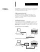
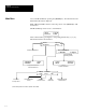
The powerup sequence is automatic, you do not have to respond to
the screens. The sequence depends upon DIP switch position #1 (upload /
download enable). The DTAM Micro is shipped with this switch On.
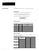
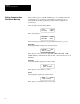
Powerup Sequence (DIP Switch #1 On)
1. The DTAM Micro verifies the system memory checksum, program
checksum, and system RAM. After the test is completed, the result is
displayed with the current DIP switch settings.
Memory Check: pass
DIP Switch: 101000
2. The display is tested, every pixel of the display is turned on.
If all of the pixels do not turn on, the display may be defective.
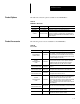
3. DTAM Micro information appears indicating the microprocessor core
firmware version and communication port (RS-232 or RS-485).
Operator Interface
Core: 3.00 RS-232
4. The DTAM Micro waits for an application download.
Programming Mode
Waiting Up/Download
Powerup Sequence (DIP Switch #1 Off)
1. The DTAM Micro verifies the system memory checksum, program
checksum, and system RAM. After the test is completed, the result is
displayed with the current DIP switch settings.
Memory Check: pass
DIP Switch: 101000
2. The display is tested, every pixel of the display is turned on.
If all of the pixels do not turn on, the display may be defective.
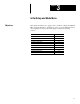
3. Operating system information appears indicating the firmware release
number and protocol being used (PLC5-DF1 or AB DH-485).
DTAM Micro (c) 1994
FRN 2.20 PLC5-DF1
4. The first application screen displays. If the DTAM Micro is being
powered up the first time you will see:
Bul. 2707 DTAM Micro
No Program Loaded
Powerup Sequence