
Operator Interface Module Instruction Manual

Chapter 2
DTAM Micro Overview
2–8
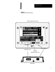
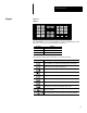
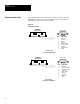
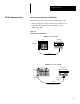
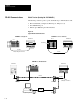
All communications are through a 9 pin connector on the bottom of the
DTAM Micro. The connector is either an RS-232 port or RS-485 port
depending upon the version catalog number.
Figure 2.5
Communications Port
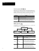
RS-485 Version
(Catalog No. 2707-M485P3)
9 Pin Female
1 Data Out –
2 Data Out +
3 Data In -
4 Data In +
5 Signal Ground
6 Transmit Enable
7 Not Used
8 Signal Ground
9 Shield
PIN # Signal Name
DTAM Micro
(Bottom View)
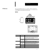
RS-232 Version
(Catalog No. 2707-M232P3)
9 Pin Female
1 Not Used
2 Receive Data (RD)
3 Transmit Data (TD)
4 Not Used
5 Signal Ground
6 Not Used
7 Not Used
8 Not Used
9 Shield
PIN # Signal Name
DTAM Micro
(Bottom View)
Communications Port