DTAM Plus Operator Interface Module Catalog Numbers 2707-L8x, 2707-L40x, 2707-V40x User Manual
Important User Information Because of the variety of uses for the products described in this publication, those responsible for the application and use of this control equipment must satisfy themselves that all necessary steps have been taken to assure that each application and use meets all performance and safety requirements, including any applicable laws, regulations, codes and standards.
Table of Contents DTAM Plus Operator Interface Module User Manual Preface Objectives . . . . . . . . . . . . . . . . . . . . . . . . . . . . . . . . . . . . . . . . . . . . . . . . . Chapter Contents . . . . . . . . . . . . . . . . . . . . . . . . . . . . . . . . . . . . . . . . . . . Intended Audience . . . . . . . . . . . . . . . . . . . . . . . . . . . . . . . . . . . . . . . . . . . Package Contents . . . . . . . . . . . . . . . . . . . . . . . . . . . . . . . . . . . . . . . . . . . Conventions . . .
Table of Contents DTAM Plus Operator Interface Module User Manual Using the Function Menu Chapter 3 Objectives . . . . . . . . . . . . . . . . . . . . . . . . . . . . . . . . . . . . . . . . . . . . . . . . . Function Key Menu . . . . . . . . . . . . . . . . . . . . . . . . . . . . . . . . . . . . . . . . . . Resetting the DTAM Plus . . . . . . . . . . . . . . . . . . . . . . . . . . . . . . . . . . . . . . To reset the DTAM Plus: . . . . . . . . . . . . . . . . . . . . . . . . . . . . . . . . . . .
Table of Contents DTAM Plus Operator Interface Module User Manual Running Applications Chapter 4 Chapter Objectives . . . . . . . . . . . . . . . . . . . . . . . . . . . . . . . . . . . . . . . . . . DIP Switch Setting . . . . . . . . . . . . . . . . . . . . . . . . . . . . . . . . . . . . . . . . . . . Application Documentation . . . . . . . . . . . . . . . . . . . . . . . . . . . . . . . . . . . . . Screen Types . . . . . . . . . . . . . . . . . . . . . . . . . . . . . . . . . . . . . . . . . . . . . .
Table of Contents DTAM Plus Operator Interface Module User Manual Communication Connections and Setup Chapter 6 Troubleshooting and Maintenance Chapter 7 iv Chapter Objectives . . . . . . . . . . . . . . . . . . . . . . . . . . . . . . . . . . . . . . . . . . 6–1 Wiring Guidelines . . . . . . . . . . . . . . . . . . . . . . . . . . . . . . . . . . . . . . . . . . . 6–1 Connecting RS-232 Devices . . . . . . . . . . . . . . . . . . . . . . . . . . . . . . . . . . . . 6–2 Connecting RS-485 Devices . . .
Table of Contents DTAM Plus Operator Interface Module User Manual Specifications Appendix A Agency Ratings . . . . . . . . . . . . . . . . . . . . . . . . . . . . . . . . . . . . . . . . . . . . . European Union Directive Compliance . . . . . . . . . . . . . . . . . . . . . . . . . . . . . DTAM Plus Cable Diagrams Appendix B DTAM Plus Cables . . . . . . . . . . . . . . . . . . . . . . . . . . . . . . . . . . . . . . . . . . . Catalog No. 2707-NC2 . . . . . . . . . . . . . . . . . . . . . . . . . . . . .
Table of Contents DTAM Plus Operator Interface Module User Manual Terminal Mode Appendix D ASCII Transmission Characters . . . . . . . . . . . . . . . . . . . . . . . . . . . . . . . . . ASCII Display Characters . . . . . . . . . . . . . . . . . . . . . . . . . . . . . . . . . . . . . .
Preface A–B Using this Manual Objectives This chapter provides an overview of this manual.
Preface Intended Audience No special knowledge is required to operate the DTAM Plus. If you are installing the DTAM Plus, you must be familiar with standard panel cutout and installation techniques. If wiring the DTAM Plus, you must be familiar with electrical codes in your area (see inside front cover). You should be familiar with the DTAM Programming Software. See related publications.
Preface Related Publications You may want to refer to the following publications for additional reference. DTAM Plus Publications Publication Number Title 2707-801 DTAM Programming Software Programming Manual (Series H or later Software) Wiring Publications 1770-6.2.2 1770-4.1 Data Highway / Data Highway Plus / Data Highway-485 Cable Installation Manual Programmable Controller Wiring and Grounding Guidelines SLC Publications Publication Number Title 1747-6.
Preface P–4
Chapter A–B 1 DTAM Plus Overview Objectives This chapter describes the DTAM Plus and accessories.
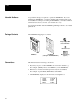
Chapter 1 DTAM Plus OverView Description The front panel of the DTAM Plus terminal is shown below. Figure 1.1 DTAM Plus (front view) Display LED Indicators Communications Port(s) Power Connector Display The 4 line by 20 character display uses either a Liquid Crystal Display (LCD) with LED backlighting or a Vacuum Fluorescent Display (VFD). You can adjust both the contrast and backlight levels on LCD displays using the keypad. You can only adjust brightness on VFD displays.
Chapter 1 DTAM Plus Overview Figure 1.2 DTAM Plus (back view) DIP Switch (Behind Removable Cover) Power Connector Communication Ports Fuses Communications Port The DTAM Plus is available with a variety of communication options as shown below. Catalog No. 2707-L8P1, -L8P2 2707-L40P1,-L40P2, -V40P1,-V40P2,-V40P2N 2707-L8P1R, -L8P2R, RS-232/485 X X Port Type Printer X X➀ 2707-L40P1R, -L40P2R, -V40P1R, -V40P2R, -V40P2NR ➀ For transferring applications only; no host communications.
Chapter 1 DTAM Plus OverView Keypad Figure 1.3 shows the DTAM Plus keypad. Figure 1.3 Keypad MAIN MENU PREV MENU PREV NEXT F Y 1 2 3 N 4 5 6 EXP 7 8 9 +/– CE 0 The keys on the DTAM Plus keypad are color coded by function. Blue keys are for navigation and operator responses; dark grey keys control display and format; and light grey keys are for numeric entry. Table 1.A Key Functions Key Function Key Function MAIN MENU Returns to the main menu of an application.
Chapter 1 DTAM Plus Overview DIP Switches The 6 position DIP switch allows you to enable or disable certain functions. Access the DIP switch by removing the cover on the back (access cover is shipped in the hardware bag on new units). Figure 1.4 DIP Switch Upload/Download Enable Communication Port Selection Master Security Enable Function Key Enable Terminal Mode Enable Comm Upload/Download Enable Side View 1 2 3 4 5 6 ON = OPEN OFF= Table 1.
Chapter 1 DTAM Plus OverView Communication Ports Versions with Comm Port The configurable communications port of the DTAM Plus supports RS-485 or RS-232. Use RS-485 to communicate with SLC processors over the Allen-Bradley DH485 network as: • one of 32 nodes on a multidrop network • direct connection to a single SLC processor or the 1746-BAS module. Communication via the 1746-BAS module provides direct backplane access and faster data throughput.
Chapter 1 DTAM Plus Overview Communication Ports Remote I/O Versions Remote I/O versions of the DTAM Plus support direct links to a PLC/SLC scanner or subscanner module on a remote I/O link. The DTAM Plus appears to the controller like a standard I/O rack. Remote I/O Communications Parameters Baud Rate Options 57.6K, 115.2K, 230.4K Rack Size 1/ , 1/ , 3/ , Full 4 2 4 Remote I/O with Printer Port Remote I/O versions with a printer port download/upload application files through the RS-232 printer port.
Chapter 1 DTAM Plus OverView RS-232 Communications Versions with a Comm Port The Comm port allows point-to-point communications with: • PLC-5 Channel 0 (configured as RS-232 port, DF1 protocol) • SLC 5/03, 5/04, 5/05, RS-232 port (DH485 protocol) Figure 1.5 RS-232 Communications DTAM Plus to PLC-5 Channel 0 PLC-5 DTAM Plus Channel 0 Comm Port (RS-232) RS-232 Cable (Catalog No. 2707-NC3) DTAM Plus to SLC 5/03 or 5/04 SLC 5/03 Channel 0 DTAM Plus Gender Adapter RS-232 Cable (Catalog No.
Chapter 1 DTAM Plus Overview RS-485 Communications Versions with a Comm Port The Comm port allows: • Point-to-point communications with a PLC-5 Channel 0 port (configured as RS-422 port, DF1 protocol) • Point-to-point or multidrop communications with an SLC controller DH-485 port Figure 1.
Chapter 1 DTAM Plus OverView Remote I/O Communications Remote I/O Versions The Remote I/O port allows you to connect the DTAM Plus to: • a PLC over a Remote I/O link • an SLC 1747-SN Scanner • a PLC-5 scanner or subscanner Figure 1.7 Remote I/O Connections DTAM Plus to PLC-5 over Remote I/O Link PLC-5 Computer Remote I/O Network Belden 9463 Cable (Catalog No.
Chapter 1 DTAM Plus Overview Default Settings The DTAM Plus is preset at the factory with the following defaults: Operating System The DTAM Plus is provided with a default DH-485 application file.
Chapter 1 DTAM Plus OverView Operating Parameters You can set the following parameters using the DTAM Plus menu functions.
Chapter 1 DTAM Plus Overview Product Options and Accessories The tables below lists the options that are available for the DTAM Plus.
Chapter 1 DTAM Plus OverView 1–14
Chapter A–B 2 Loading an Application Objectives This chapter describes how to apply power and transfer applications between the offline programing software (DPS) and the DTAM Plus.
Chapter 2 Loading an Application Applying Power To apply power to the DTAM Plus: 1. Connect the ground, neutral, and hot lines as shown below. Verify the connections by checking the power supply label on the back of the DTAM Plus. DTAM Plus (40K Remote I/O Version Shown, Others Are Similar) For DC connections, connect the Positive Lead to Hot and the Negative lead to NEU. 2. Apply power. The DTAM Plus performs a powerup sequence.
Chapter 2 Loading an Application Powerup Sequence The powerup sequence is automatic. The sequence depends upon the setting of DIP switch position SW-1 (upload / download enable). The DTAM Plus is shipped with SW-1 On. Powerup Sequence (DIP Switch SW-1 ON) The following steps show the powerup sequence if DIP switch SW-1 is ON. 1. The DTAM Plus verifies the system memory checksum, program checksum, and system RAM. When done, the result is displayed with the current DIP switch settings.
Chapter 2 Loading an Application Powerup Sequence (DIP Switch SW-1 OFF) The following steps show the powerup sequence if DIP switch SW-1 is OFF. 1. The DTAM Plus verifies the system memory checksum, program checksum, and system RAM. After the test is completed, the result is displayed with the current DIP switch settings. Checksum: passed DIP Switch: 001000 RAM: pass 40K User Memory 2. The display is tested, every pixel of the display is turned on.
Chapter 2 Loading an Application Upload / Download DIP Switch Settings Before you can upload or download an application, you must verify that DIP switch SW-1 is ON. (DTAM Plus is shipped in this position). To access the DIP switch, remove the cover from the access hole on the back of the DTAM Plus (align cover tabs with notches in hole to remove). The DTAM Plus is shipped without the cover installed, you can find it in the hardware bag.
Chapter 2 Loading an Application Upload / Download RS-232 Connections To connect a DTAM Plus RS-232 port to a computer, use the RS-232 Upload/Download cable (Catalog No. 2707-NC2). Use the communications or printer port (see below). You may need a 9-to-25 pin adapter to connect the cable to your computer. A male to female gender adapter is required to connect the cable to the printer port or you can create your own cable. Appendix B provides cable diagrams.
Chapter 2 Loading an Application Upload / Download RS-485 Connections Versions with a Comm Port It’s recommended that you use the RS-232 port for transferring applications. On DTAM Plus versions with a Comm (RS-485 / RS-232) port, you can also download applications using an RS-485 connection.
Chapter 2 Loading an Application Downloading an Application This section shows how to download an application from a computer running DPS software to the DTAM Plus. Refer to the DPS Programming Manual (Publication No. 2707-801) for additional information. To download an application: 1. Apply power to the DTAM Plus. The following message appears. Programming Mode Waiting Up/Download If you do not see this message, check the DIP switch settings. DIP Switch SW-1 must be ON. 2.
Chapter 2 Loading an Application 6. Press any key (other than [Esc]) to continue. The Product Selection Menu appears. . You will not see this prompt if a product type was specified during installation. 7. Press the down arrow [ # ] and [Return] to select the DTAM Plus product. The Opening Menu appears.
Chapter 2 Loading an Application Downloading an Application 8. Highlight Download File to DTAM Plus and press [Return]. The Communication Port Selection screen appears. . You will not see this screen if a communication port was specified during DPS installation. 9. Highlight the serial port on your computer that is connected to the DTAM Plus (COMM 1 or COMM 2) and press [Return]. ☞ If a communication link does not 10.
Chapter 2 Loading an Application 12. Select a file and press [Return] to load the application file. The download begins and the following screen shows the progress of the download operation. 13.
Chapter 2 Loading an Application 14. When the download is complete, you return to the Opening Menu. and the DTAM Plus displays: Programming Mode Waiting Up/Download 15. Press [Esc] to exit the software. 16. Press [Y] to return to DOS. The application is now loaded in the DTAM Plus. You can test the application using the simulate function described in Chapter 4 or you can run the application as described in Chapter 5. Important: To run the application, set DIP switch SW-1 OFF.
Chapter 2 Loading an Application Uploading an Application This section shows how to upload an application from the DTAM Plus to a computer running DPS software (Catalog No. 2707-NP). Refer to the DPS User manual (Publication No. 2707-801) for additional instructions. To upload an application: 1. Apply power to the DTAM Plus. The following message appears. Programming Mode Waiting Up/Download If you do not see this message, check the DIP switch settings. DIP Switch SW-1 must be ON. 2.
Chapter 2 Loading an Application 6. Press any key (other than [Esc]) to continue. The Product Selection Menu appears. . You will not see this prompt if a product type was specified during installation. 7. Press the down arrow [ # ] and [Return] to select the DTAM Plus product. The Opening Menu appears.
Chapter 2 Loading an Application 8. Highlight Upload File from DTAM Plus and press [Return]. The Communication Port Selection screen appears. . You will not see this screen if a communication port was specified during DPS installation. 9. Highlight the serial port on your computer that is connected to the DTAM Plus (COMM 1 or COMM 2) and press [Return]. 10. The upload begins and the following screen shows the progress of the upload operation. 11. You are prompted for the application file name.
Chapter 2 Loading an Application 12. When the upload is complete, you return to the Opening Menu. 13. Press [Esc] to exit the software. 14. Press [Y] to return to DOS. The application is now loaded into the DPS software. You can edit the application as described in the DPS Programming Manual (Publication No. 2707-801).
Chapter A–B 3 Using the Function Menu Objectives This chapter describes how to perform operations from the Function menu and contains the following sections: Section Page Function Key Menu 3–2 Resetting the DTAM Plus 3–3 Setting Communication Port Parameters 3–4 Displaying Remote I/O Port Parameters 3–5 Setting Printer Port Parameters 3–7 Enabling Screen Prints 3–9 Setting the Clock Calendar 3–10 Adjusting the Display Contrast 3–11 Adjusting the Display Brightness 3–12 Enabling Simul
Chapter 3 Using the Function Menu Function Key Menu Many DTAM Plus functions are accessed from the Function menu. To access the Function menu, press the [F] key on the keypad. All other functions are halted when the menu is displayed. Note: To enable the F (Function) key, DIP switch SW-4 must be set ON. The Function menu provides access to these functions: 1 C-Port 2 P-Port 3 Clk/Cal 4 Reset 5 Special 6 Term 7 Test 8 Other Select a menu item by pressing the corresponding numeric key [1] ! [8].
Chapter 3 Using the Function Menu Resetting the DTAM Plus Use the Reset function to reset the DTAM Plus after DIP switch changes or a configuration change using the Function Key Menu. You can also use the Reset function to activate Terminal Mode if DIP switch SW-5 is set ON. To reset the DTAM Plus: 1. From the Function Menu, select Reset [4]. 1 C-Port 2 P-Port 3 Clk/Cal 4 Reset 5 Special 6 Term 7 Test 8 Other This screen appears: Press ”Y” To Reset Press ”N” To Abort 2.
Chapter 3 Using the Function Menu Setting Communication Port Parameters The C-Port option on the Function Menu lets you manually adjust the communication port parameters. Normally these parameters are set from the DPS programming software when an application is downloaded. Select C-Port [1] from the Function Menu.
Chapter 3 Using the Function Menu Displaying Remote I/O Port Parameters The R–Port option allows you to display (not modify) Remote I/O parameters for the DTAM Plus. These parameters are set from the programming software when an application is downloaded. The R–Port option is only available for versions with a Remote I/O port. To display Remote I/O communication parameters: 1. Select Special [5] from the Function Menu.
Chapter 3 Using the Function Menu Last Rack Selecting LastRack [3] shows whether the DTAM Plus is configured as the last rack. Is Last Rack YES ”ENTER” To Continue Rack Number Selecting RackNum [4] displays the current rack number of the DTAM Plus. Rack Number 02 ”ENTER” To Continue Module Group Selecting ModuGrp [5] displays the starting module group of the DTAM Plus. Module Group 0 ”ENTER” To Continue Reset Selecting Reset [6] restarts the DTAM Plus (same as cycling power).
Chapter 3 Using the Function Menu Setting Printer Port Parameters The P-Port option on the Function Menu lets you manually set the RS-232 printer port parameters. Normally these parameters are set automatically from the DPS programming software when an application is downloaded. This menu options is only valid for versions that have a printer port. Select P-Port [2] from the Function Menu.
Chapter 3 Using the Function Menu Parity Selecting Parity [3] displays the current setting. Select Parity: Parity None ”NEXT” To Change ”ENTER” To Select Press [NEXT] to change between Even, Odd, or No parity. Press [ select a new parity. ] to Handshake Selecting Hndshk [4] enables/disables handshaking. Handshaking is a request to send a communications signal (RTS) and notification that a transmission may be sent (CTS).
Chapter 3 Using the Function Menu Enabling Screen Prints The Prn Scrn option allows you to send the current display screen to the printer port when the [EXP] key is pressed on the keypad. When the Prn Scrn option is disabled, you can only use the [EXP] key to enter floating point data. This menu options is only valid for versions that have a printer port. To enable printing of screens: 1. Select Other [5] from the Function menu.
Chapter 3 Using the Function Menu Setting the Clock/Calendar The Clk/Cal option on the Function Menu lets you set and display the internal real time clock of the DTAM Plus (only on versions with clock option). The real time clock provides time and date information for DTAM Plus operations. You can also insert the time and date in operator screens and print forms. Refer to your controller documentation for more details on time synchronization.
Chapter 3 Using the Function Menu Adjusting the Display Contrast (LCD versions only) The Contrast option on the Other menu enables or disables the contrast adjustment the of the LCD display from the contrast key. Any adjustments to the contrast from the keypad are maintained after power is cycled to the DTAM Plus. If disabled, the contrast and backlight intensity remain at their current setting and cannot be changed from the keypad.
Chapter 3 Using the Function Menu Adjusting the Display Brightness The BL / INT option on the Other menu enables or disables the backlighting (LCD versions) or character intensity (VFD versions) adjustment from the keypad. Any adjustments to the brightness from the keypad are maintained after power is cycled to the DTAM Plus. If disabled, the brightness remains at its current setting and cannot be changed from the keypad. To enable brightness adjustments from the keypad: 1.
Chapter 3 Using the Function Menu Enabling Simulate Mode Use the Simulate mode to check an application without having a controller connected. All data normally sent by the controller, such as data for a display, is set to 0. Simulate mode: • halts communication between the DTAM Plus and the controller. • simulates communication with a controller. Disabling the Simulate mode resumes normal DTAM Plus operation. To simulate an application: 1. Download the application from the DPS software. 2.
Chapter 3 Using the Function Menu Enabling Terminal Mode The Term option on the Function Menu lets you set communication and display parameters for using the DTAM Plus in terminal mode. Terminal Mode disables execution of the application program and enables the DTAM Plus to function as a terminal device. In Terminal mode, the DTAM Plus displays any ASCII data received through the communications port.
Chapter 3 Using the Function Menu Line Feed Enable Selecting L/Feed [2] enables/disables Line Feed. When enabled, The DTAM Plus sends a line feed (LF) and carriage return (CR) each time a carriage return is received. When disabled, only a carriage return is sent. L/Feed Enable OFF (0) ”1” or ”Y” = ON ”0” or ”N” = OFF ENTER = NC Press [1] or [Y] to enable a line feed. Press [0] or [N] to disable a line feed. Press [ ] to return to P-Port menu without any change.
Chapter 3 Using the Function Menu Entering a New Master Security Code The Special [5] menu item on the function menu may be password protected to restrict access to the P-A/D feature. When an application has a security screen, the operator will be prompted for a security code. The master security code provides access to the Special menu and all other security codes allowing them to be modified.
Chapter 3 Using the Function Menu Note: Security codes can contain the wildcard character “?”. Any entered value will be seen as a match to the wildcard. The master security code must be different from security codes using wildcard entries. Otherwise the master security code may be seen as a security code. For example: Security Code =12?????? Master Code = 12368794 When the master security code above is entered, the DTAM Plus interprets it as a security code. 5. Press [ ] to return to the Other menu. 6.
Chapter 3 Using the Function Menu Using Scaling Use scaling to convert data from a controller to engineering units such as gallons or psi. When scaling is disabled, the values are not converted. Refer to the DTAM Programming Software Manual for a description of how values are scaled. The scaling factor is determined by the application designer, it cannot be changed by the operator.
Chapter 3 Using the Function Menu Accessing the Point/Access Display Function The Point - Access / Display function allows you to display and modify controller data files. The P-A/D function does not allow you to write controller Input and Output files. Appendix C provides a listing of the applicable file types for SLC and PLC-5 controllers, along with step-by-step instructions on how to use the P-A/D function. To access the Point - Access/Display Function: 1. From the Function Menu, select Special [5].
Chapter 3 Using the Function Menu Accessing Test Functions Use the Test menu to perform variety of tests that check the status of the DTAM Plus functions and hardware. You can access all of the Test options from the Function menu. This section shows how to access the test functions. For details on how to perform each test, see Chapter 7 Troubleshooting and Maintenance. To access the Test functions: From the Function Menu, select Test [7].
Chapter A–B 4 Running Applications Chapter Objectives This chapter describes screen types and operating procedures that are common to most applications.
Chapter 4 Running Applications Screen Types Application screens can have a variety of appearances. The DTAM Plus can display seven types of screens.
Chapter 4 Running Applications Menu and Sub-Menu Screens Menus and Sub-Menus provide a convenient method of accessing a large number of display screens. Main Menu Every application has a Main Menu screen. The Main Menu is the first application screen displayed after an initial power-up or reset. 1 2 3 4 Pump Tank Stat Mixer Stat Recipe The Main Menu provides access to the next level of screens and Sub-Menus. To access the Main Menu, press the [MAIN MENU] key.
Chapter 4 Running Applications Data Display Screens Data display screens show either the actual or scaled value of a logic controller data address. Data Display Field Pump 1 Pressure = 150 PSI Counter = 5 Data Display Field Data displays are updated at different intervals depending upon the application and the size of the network. Bar Graph Screens Bar graph displays provide a graphical representation of an actual or scaled value at a logic controller data address.
Chapter 4 Running Applications ASCII Input The DTAM Plus allows ASCII data to be directly entered from a device such as a bar code scanner. An ASCII entry screen looks like a standard data entry display. When the ASCII input screen is displayed, data can then be entered through the ASCII device connected to the printer port using the 2707-NC6 cable. Here are some items you should note when using a bar code scanner as an input device for data entry fields.
Chapter 4 Running Applications Recipe Screens Recipe screens allow the DTAM Plus to write to multiple controller addresses in one operation. Recipe screens can also be linked so that more than one recipe is downloaded. Download Recipe 323? Press ENTER to send T4:14.2 (Timer Value) N7:30 = 0 (Integer Value) N7:31 = 100 (Integer Value) T4:15.
Chapter A–B 5 Installation Objectives This chapter contains the following sections: Section Safety Guidelines Page Safety Guidelines 5–1 Operating Environment 5–2 Enclosures 5–3 Equipment Required 5–3 Clearances 5–3 Mounting Dimensions 5–4 Cutout Template 5–5 Installation 5–6 Connecting Power 5–7 Install the DTAM Plus using publication NFPA 70E, Electrical Safety Requirements for Employee Workplaces as a guide.
Chapter 5 Installation ! ATTENTION: EXPLOSION HAZARD: SUBSTITUTION OF COMPONENTS MAY IMPAIR SUITABILITY FOR CLASS 1, DIVISION 2. RISQUE D’EXPLOSION: LA SUBSTITUTION DE COMPOSANTS PEUT RENDRE CE MATÉRIEL INACCEPTABLE POUR LES EMPLACEMENTS DE CLASSE 1, DIVISION 2. ! ATTENTION: USE P1 POWERED UNITS ONLY WITH CLASS 2 POWER SOURCE LIMITED TO 30 VDC OPEN CIRCUIT AND 8A SHORT CIRCUIT.
Chapter 5 Installation Enclosures The terminal must be mounted in a panel or enclosure to protect the internal circuitry. The terminal meets NEMA Type 4, 12, 13 (indoor use only) or 4X (indoor 2707-V40P2N, -V40P2NR) ratings only when mounted in a panel or enclosure with the equivalent rating. Allow enough spacing within an enclosure for adequate ventilation. For some applications, you may have to consider heat produced by other devices within a panel.
Chapter 5 Installation Mounting Dimensions Figure 5.2 shows the mounting dimensions of the terminal. Figure 5.2 Mounting Dimensions in Inches (Millimeters) Back View 7.876 (200.1) 8.50 (215.9) 6.9 (175.3) Bottom View 5.5 (139.7) 5.5 (139.7) 2.35 (59.7) 2.0 (50.
Chapter 5 Installation Cutout Template A cutout template is provided on the inside back cover of this manual to mark the cutout dimensions. Figure 5.3 provides a reference copy, don’t remove this page from the manual. Figure 5.
Chapter 5 Installation Installation To install the DTAM Plus Operator Module: ! ATTENTION: Disconnect all electrical power from the panel before making cutout. Make sure that area around panel cutout is clear. Take precautions so that metal filings or other debris do not fall into the DTAM Plus ventilation slots or enter any components that may already be installed in panel. Make sure that no objects are inserted or fall into the terminal through the ventilation slots or DIP switch access hole.
Chapter 5 Installation Wire and Cable Length Restrictions The following wire and cable length restrictions apply to DTAM products that are CE marked when used in installations that require compliance to European EMC Directive 89/336: DC Power Wiring 10 meters Ground Terminal Wire 3 meters Communication Cables 30 meters These restrictions apply to the following catalog numbers: 2707–L8P1 Series D, 2707–L40P1 Series D and 2707–V40P1 Series D.
Chapter 5 Installation Figure 5.4 Power Connections DTAM Plus (40K Remote I/O Version Shown, Others Are Similar) For DC connections, connect the Positive Lead to Hot and the Negative lead to NEU. 3. Connect communications cabling as described in Chapter 6. 4. Apply voltage and verify the DTAM Plus powerup sequence as described in Chapter 2.
Chapter A–B 6 Communication Connections and Setup Chapter Objectives This chapter describes how to connect the DTAM Plus to peripheral devices.
Chapter 6 Communication Connections and Setup Connecting RS-232 Devices The RS-232 Comm port of the DTAM Plus allows point-to-point communications with: • PLC-5 Channel 0 (configured as RS-232 port) • SLC 5/03, 5/04, 5/05 Channel 0 (configured as RS-232 port) • MicroLogix 1000 The figure below shows typical RS-232 connections. DTAM Plus to PLC5 Channel 0 PLC-5 DTAM Plus Channel 0 Comm Port RS-232 Cable (Catalog No.
Chapter 6 Communication Connections and Setup Connecting RS-485 Devices The RS-485 Comm port allows: • Point-to-point communications with a PLC-5 Channel 0 port • Point-to-point or multidrop communications with an SLC controller DH-485 port • MicroLogix 1000 using the AIC+ Interface The figure below shows typical RS-485 connections. DTAM Plus to PLC5 Channel 0 (Point-to-Point Only) PLC-5 DTAM Plus Channel 0 RS-422 Comm Port RS-485 RS-422 Cable (Catalog No.
Chapter 6 Communication Connections and Setup DTAM Plus to DH-485 Network (Multidrop) DTAM Plus DTAM Plus Catalog No. 2707-V40P2 SLC 5/01 Cable (Catalog No. 2707-NC1) Cable (Catalog No. 2707-NC1) DH485 Network RS-485 RS-485 Link Coupler Link Coupler Interface Converter Programming Terminal RS-232 to RS-485 Link Coupler To connect the DTAM Plus terminal to an RS-485 device: 1. Make sure that the power to the DTAM Plus is off. 2.
Chapter 6 Communication Connections and Setup Connecting Remote I/O Devices The Remote I/O port of the DTAM Plus provides access via a Remote I/O link directly to a controller or subscanner. Use cable (Catalog No. 1770-CD) Belden 9463 for all Remote I/O connections. Refer to Publication No. 1770-4.1 for detailed grounding and wiring guidelines. The user manual for your controller or subscanner will also provide cabling instructions. The following figures show typical Remote I/O connections.
Chapter 6 Communication Connections and Setup Communicating with a Logic Controller The DTAM Plus supports four operating systems. • • • • Remote I/O PLC5-DF1 AB BASIC AB DH-485 protocol The type of operating system supported by the DTAM Plus depends upon its communication configuration. DTAM Plus Version Operating System Controller Type RS-485 / RS-232 Versions (Catalog No.
Chapter 6 Communication Connections and Setup RS-232 or RS-422 Communications With a PLC-5 The DTAM Plus and PLC-5 must be set as follows for communications to occur: PLC-5 Channel 0 RS–232 or RS-422 DTAM Plus RS-232 / RS-485 Versions RS-232 or RS-485 Cable Use Catalog No. 2707-NC3 for RS-232 Use Catalog No. 2707–NC4 for RS-422 DTAM Plus The DTAM Plus must have an application with a PLC-5 (DF1) operating system installed. The Baud Rate and Parity of the DTAM Plus and PLC-5 must be the same.
Chapter 6 Communication Connections and Setup RS-232 Communications with an SLC 5/03, -5/04, -5/05 The DTAM Plus and RS-232 port of the SLC 5/03, 5/04, 5/05 must be set as follows for communications to occur: DTAM Plus RS-232 / RS-485 Versions SLC 5/03, 5/04, 5/05 Comm Port Channel 0 Gender Adapter RS-232C Cable (Catalog No. 1747-CP3) Gender Adapter Required DTAM Plus The DTAM Plus must have an application with AB DH485 operating system installed.
Chapter 6 Communication Connections and Setup DH-485 Communications with an SLC 500 or Network The DTAM Plus and SLC 500 DH-485 port must be set as follows for communications to occur. If you are using an SLC 5/03, 5/04, 5/05 RS-232 port, refer to the previous section. DTAM Plus RS-232 / RS-485 Versions SLC 500 RS-485 Cable (Catalog No. 2707-NC1) Comm Port DTAM Plus RS-232 / RS-485 Versions DH-485 Network DH-485 Network SLC 500 Link Coupler Link Coupler Comm Port RS-485 Cable (Catalog No.
Chapter 6 Communication Connections and Setup SLC 5/03, 5/04, 5/05 (channel 0) Make sure that the SLC DH-485 port is configured as follows: Parameter Selections Recommended Baud Rate 1200, 2400, 9600, 19.2K 19.2K Node Address 0 to 31 Next lowest address on the network. Set to 1 for point-to point communications ①. Maximum Node Address 0 to 31 Set to maximum node on network. Set to 1 for point-to point communications ①.
Chapter 6 Communication Connections and Setup RS–485/DH–485 Communications with a MicroLogix 1000 The DTAM Plus must be set as follows for communication to occur. The DTAM module uses DH485 protocol but the comm port is set for RS-485 (switch 1 position 2 is on). This is a 3-node network and is not expandable. DTAM Plus MicroLogix 1000 AIC+ DH485 Comm Port (RS485) RS232 Cable (Catalog No.
Chapter 6 Communication Connections and Setup 6–12
Chapter A–B 7 Troubleshooting and Maintenance Chapter Objectives This chapter describes how to isolate and correct the most common operating problems and routine maintenance tasks.
Chapter 7 Troubleshooting and Maintenance Common Operating Problems If there is no display on the DTAM Plus, verify that the proper voltage is present at the DTAM Plus power supply terminal block (check label on back of unit). If no voltage is present, check the power to/from the power source. The most common DTAM Plus problems are related to cabling configurations and the communication parameters (baud rate, data bits, parity). These parameters must be identical for both the DTAM Plus and the controller.
Chapter 7 Troubleshooting and Maintenance Message Probable Cause(s) Corrective Action(s) Com Error Code: nnH Press ENTER to Reset Communication error code (nn) Received a controller error code. Refer to next section for error codes. Attempt Was Made to ’Call’ An Invalid Or Unprogrammed Screen Illegal or unprogrammed screen type detected (.CFG file error). Check the program (.CFG) file and download. Check screen links. NAchip Set:Failed Internal fault. Contact Allen-Bradley for technical support.
Chapter 7 Troubleshooting and Maintenance Communication Error Codes Communication Error Codes appear on the DTAM Plus display as follows: Error Code Com Error Code: nnH Press ENTER to Reset The error code is in the form: • nnH for SLC controllers that do not show extended error codes. • X nnH for PLC controllers. The X indicates an extended error code. The communication error codes provide valuable information when other symptoms either have not been discovered or have not been understood.
Chapter 7 Troubleshooting and Maintenance Using the Test Functions Use the test selection screen to test or check the following: • • • • • • • • • • • • Reset DUT (resets terminal, terminates test function) DIP switch positions Display Keyboard Comm port Printer port Display control Random Access Memory System memory Program file Clock/calendar Transmit enable & Alarm To access the test functions: 1. Access the Test functions from the Functions Menu.
Chapter 7 Troubleshooting and Maintenance DIP Switch Test Use the DIP switch test to verify the DIP switch positions. To perform the DIP switch test: 1. Use the [NEXT] and [PREV] keys to display DIP Switch on the test selection screen. DTAM Plus Diagnostic NEXT to Select Test ENTER To Initiate Dipswitch 2. Press [ ] to initiate the test. The DTAM Plus displays the current DIP switch settings.
Chapter 7 Troubleshooting and Maintenance Display Test Use the display test to verify that each screen pixel is operating properly. To perform the display test: 1. Use the [NEXT] or [PREV] keys to show Display on the test selection screen. DTAM Plus Diagnostic NEXT to Select Test ENTER To Initiate Display Test 2. Press [ ] to initiate the test. The DTAM Plus turns all pixels on and then off. Then an alternate checkerboard pattern is displayed: 3. Press [ ] to terminate the test.
Chapter 7 Troubleshooting and Maintenance Keyboard Test Use the keyboard test to verify that the keyboard is functioning properly. To perform the keyboard test: 1. Use the [NEXT] or [PREV] keys to display Keyboard on the test selection screen. DTAM Plus Diagnostic NEXT to Select Test ENTER To Initiate Keyboard 2. Press [ ] to initiate the test. The DTAM Plus prompts you to press each key in a sequential order. Press ”MAIN MENU” 3. Press the keys as prompted form left to right beginning at the top.
Chapter 7 Troubleshooting and Maintenance Comm Port Test Use the communications test to verify the operation of the RS-232/ RS-485 Comm port. The communications test requires a loopback connector.
Chapter 7 Troubleshooting and Maintenance Printer Port Test Use the Printer Port test to verify the operation of the printer port The test requires a loopback connector. You can construct a simple loopback connector as follows: RS-232 Port 9-Pin Male Pin# 1 2 3 4 5 6 7 8 9 Signal Name Not Used Receive Data (RD) Transmit Data (TD) Not Used Signal Ground Not Used Not Used Not Used Shield Loopback Connector Connects pins 2 !3 To test the printer port: 1.
Chapter 7 Troubleshooting and Maintenance Display Control Test Use the Display Control test to test the brightness and contrast settings of the display. 1. Use the [NEXT] or [PREV] keys until Display Control appears on the test selection screen. DTAM Plus Diagnostic NEXT to Select Test ENTER To Initiate Display Control 2. Press [ ] to initiate the test.
Chapter 7 Troubleshooting and Maintenance RAM Test Use the RAM test to verify the DTAM Plus Random Access Memory. 1. Use the [NEXT] or [PREV] keys to display RAM on the test selection screen. DTAM Plus Diagnostic NEXT to Select Test ENTER To Initiate RAM Test 2. Press [ ] to initiate the test. The DTAM Plus displays either a Pass or Fail message. RAM: Pass Press ENTER 3. Pressing [ ] terminates the RAM test. The next test selection screen is displayed.
Chapter 7 Troubleshooting and Maintenance System Memory Test Use the System Memory test to verify the checksum of the operating system. 1. Use the [NEXT] or [PREV] keys to display System Memory test on the test selection screen. DTAM Plus Diagnostic NEXT to Select Test ENTER To Initiate System Memory 2. Press [ ] to initiate the test. The DTAM Plus displays either a Pass or Fail message. Checksum: passed Press ENTER 3. Pressing [ ] terminates the System Memory test.
Chapter 7 Troubleshooting and Maintenance Program File Test Use the Program Memory test to verify the checksum of the current application file. 1. Use the [NEXT] or [PREV] keys to display Program File test on the test selection screen. DTAM Plus Diagnostic NEXT to Select Test ENTER To Initiate Program File 2. Press [ ] to initiate the test. The screen displays the amount of memory in the DTAM Plus and performs a checksum test. 40k User Memory Checksum:passed Press ENTER 3.
Chapter 7 Troubleshooting and Maintenance Clock/Calendar Test Use the Clock/Calendar test to test the realtime clock in the DTAM Plus. This test is valid only for terminals with a realtime clock. 1. Use the [NEXT] or [PREV] keys to display Clock/Calendar test on the test selection screen. DTAM Plus Diagnostic NEXT to Select Test ENTER To Initiate Clock/Calendar 2. Press [ ] to initiate the test. The screen displays the current time and date. TIME DATE 01:17:25 Wed Aug 12 98 Press ENTER 3.
Chapter 7 Troubleshooting and Maintenance TXEN Test Only available on the RS-485 Comm port version. Use the TXEN test to verify the transmit enable line at the RS-485 communications port. The TXEN test requires a loopback connector with an LED.
Chapter 7 Troubleshooting and Maintenance Cleaning the Display Window To clean the display window: ! ATTENTION: Use of abrasive cleansers or solvents may damage the window. Do not scrub or use brushes. Some types of paper towels may scratch the window, only use a soft sponge or cloth. 1. Disconnect power from the DTAM Plus at the power source. 2. Using a clean sponge or a soft cloth, clean the display with a mild soap or detergent. 3.
Chapter 7 Troubleshooting and Maintenance 7–18
Appendix A–B A Specifications DTAM Plus Specifications Display Column and Character Display Technology LCD (2707-L versions) 4 lines x 20 characters Twisted-nematic type with adjustable LED (yellow) backlighting Vacuum Fluorescent Display with viewing distance that exceeds 25 feet (7.
Appendix A Specifications Environmental Ambient Temperature Rating Operating LCD Display VFD Display Storage 0 to +45° C (32 to 113° F) 0 to +60° C (32 to 140° F) -20 to +85° C (-4 to 185° F) Relative Humidity 5 to 95%, noncondensing Mechanical Dimensions (Approximate) Height: Width: Depth: RS-232 / RS 485 Versions Remote I/O Versions 7.6 inch (193.0 mm) 5.5 inch (139.7 mm) 1.8 inch (45.7 mm) 2.35 inch (59.7 mm) Front Panel Size: Height: Width: 8.5 inch (215.9 mm) 6.5 inch (165.
Appendix A Specifications European Union Directive Compliance If this product is installed within the European Union or EFTA regions, the following regulations apply.
Appendix A Specifications A–4
Appendix A–B B DTAM Plus Cable Diagrams DTAM Plus Cables Catalog No. 2707-NC1 Use the DH-485 Network Interface Cable to connect the RS-232/RS-485 versions of the DTAM Plus to an SLC DH-485 network.
Appendix B DTAM Plus Cable Diagrams Catalog No. 2707-NC3 Use the RS-232 Communications Cable to connect the RS-232/RS-485 versions of the DTAM Plus to Channel 0 (configured as RS-232) of a PLC-5. DTAM Plus RS-232 Comm Port PLC-5 Channel 0 Port RS-232 Data In 2 2 Data Out Data Out 3 3 Data In Signal Ground 5 7 Signal Ground 4 RTS CTS 9-Pin Male D Connector 5 Handshake lines only required if Handshake is enabled in PLC. 8 DSR DCD 20 DTR 6 25-Pin Male D Connector Catalog No.
Appendix B DTAM Plus Cable Diagrams Catalog No. 2707-NC6 Use the ASCII Input cable to connect an ASCII device to the DTAM Plus printer port. Use this cable with decoded bar code scanners.
Appendix B DTAM Plus Cable Diagrams Catalog No. 2707-NC10 Use the RS-232 Communications cable (Catalog No. 2707-NC10) to connect the DTAM Plus to the MicroLogix 1000 for run-time operation. The length of this cable is 2 meters.
Appendix B DTAM Plus Cable Diagrams Catalog No. 1747-CP3 Use this RS-232 Communications Cable to connect the RS-232 Comm port of the DTAM Plus to Channel 0 of an SLC 5/03, 5/04. A 9 pin male to female gender adapter is required when using this cable. If you are making your own cable, use a 9 pin male connector on the DTAM Plus end instead of the 9 pin female connector (with 90_ bend allowing closure of the SLC door) shown below. In addition, the control lines are not needed.
Appendix B DTAM Plus Cable Diagrams DTAM Plus RS-232 Printer Port Cable Create the following cable for the optional printer port of the DTAM Plus. Use this port to send data to a printer or serial device such as a large display.
Appendix A–B C Special Controller Functions Objectives This appendix describes the Special Menu used to access to special features for controller operations.
Appendix C Special Controller Functions Accessing Special Functions To access the Special Functions Menu: 1. Select item 5 from the Function Menu to access the Special Menu: 1 C-Port 2 P-Port 3 Clk/Cal 4 Reset 5 Special 6 Term 7 Test 8 Other You are prompted: Remote I/O Operating System 1. P – A/D 2. R – PORT DH485 Operating System SLC 50X Network Addr Press ”Y’ to Edit Address ”N” to Bypass PLC-5 DF1 Operating System 1. P – A/D 2. PLC Mode 3. Memory Transfer 4.
Appendix C Special Controller Functions Using the P-A/D Function Use the P-A/D function to display and change values in controller files. The only exceptions are Input and Output files, you cannot write to these file types. The P-A/D function is often useful when starting up or debugging applications.
Appendix C Special Controller Functions Reading Controller Input and Output Files To read the contents of controller Input and Output files: 1. Enter the P–A/D function from the Special Menu. You are prompted for a file type: Select file type: (O)Output PREV/NEXT To Scroll ENTER To Select 2. Press [NEXT] and [PREV] keys to scroll through the file types. ].
Appendix C Special Controller Functions Reading / Writing Controller Status Files To read/write the contents of controller Status files: ATTENTION: Changing control status bits may cause a processor fault or have other possible effects on the controller operation. Make sure you understand the function of status data. ! 1. Enter the P–A/D function from the Special Menu. You are prompted for a file type: Select file type: (O)Output PREV/NEXT To Scroll ENTER To Select 2.
Appendix C Special Controller Functions Reading / Writing Controller Bit and Integer Files To read/write the contents of controller Bit and Integer files: 1. Select item 1 from the Special Menu to access the P–A/D function. You are prompted for a file type: Select file type: (O)Output PREV/NEXT To Scroll ENTER To Select 2. Press [NEXT] and [PREV] keys to scroll through the file types. Select either (B)Bit or (N)Integer and press [ ].
Appendix C Special Controller Functions Reading / Writing Controller Timer Files To read/write the contents of controller Timer files: 1. Select item 1 from the Special Menu to access the P–A/D function. You are prompted for a file type: Select file type: (O)Output PREV/NEXT To Scroll ENTER To Select 2. Press [NEXT] and [PREV] keys to scroll through the file types. Select (T)Timer and press [ ].
Appendix C Special Controller Functions Reading / Writing Controller Counter Files To read/write the contents of controller Counter files: 1. Select item 1 from the Special Menu to access the P–A/D function. You are prompted for a file type: Select file type: (O)Output PREV/NEXT To Scroll ENTER To Select 2. Press [NEXT] and [PREV] keys to scroll through the file types. Select (C) Counter and press [ ].
Appendix C Special Controller Functions Reading / Writing Controller Control Files To read/write the contents of controller Control files: 1. Select item 1 from the Special Menu to access the P–A/D function. You are prompted for a file type: Select file type: (O)Output PREV/NEXT To Scroll ENTER To Select 2. Press [NEXT] and [PREV] keys to scroll through the file types. Select (R)Control and press [ ].
Appendix C Special Controller Functions Reading / Writing Floating Point Files To read the contents of Floating Point files: 1. Select item 1 from the Special Menu to access the P–A/D function. You are prompted for a file type: Select file type: (O)Output PREV/NEXT To Scroll ENTER To Select 2. Press [NEXT] and [PREV] keys to scroll through the file types. Select (F)Float and press [ ].
Appendix C Special Controller Functions Reading / Writing Controller ASCII Files To read the contents of ASCII files: 1. Select item 1 from the Special Menu to access the P–A/D function. You are prompted for a file type: Select file type: (O)Output PREV/NEXT To Scroll ENTER To Select 2. Press [NEXT] and [PREV] keys to scroll through the file types. Select (A)ASCII and press [ ].
Appendix C Special Controller Functions Reading / Writing Controller BCD Files To read/write the contents of controller BCD files: 1. Select item 1 from the Special Menu to access the P–A/D function. You are prompted for a file type: Select file type: (O)Output PREV/NEXT To Scroll ENTER To Select 2. Press [NEXT] and [PREV] keys to scroll through the file types. Select (D)BCD and press [ ].
Appendix C Special Controller Functions Reading / Writing Controller Block Transfer Files To read/write the contents of PLC controller Block Transfer Read or Write files: 1. Select item 1 from the Special Menu to access the P–A/D function. You are prompted for a file type: Select file type: (O)Output PREV/NEXT To Scroll ENTER To Select 2. Press [NEXT] and [PREV] keys to scroll through the file types. Select (BT, BTR, or BTW) Block Xfer and press [ ].
Appendix C Special Controller Functions Reading / Writing Controller Message Files To read the contents of PLC message files: 1. Select item 1 from the Special Menu to access the P–A/D function. You are prompted for a file type: Select file type: (O)Output PREV/NEXT To Scroll ENTER To Select 2. Press [NEXT] and [PREV] keys to scroll through the file types. Select (MG)Message and press [ ].
Appendix C Special Controller Functions Reading / Writing PID Files To read the contents of PLC PID files: 1. Select item 1 from the Special Menu to access the P–A/D function. You are prompted for a file type: Select file type: (O)Output PREV/NEXT To Scroll ENTER To Select 2. Press [NEXT] and [PREV] keys to scroll through the file types. Select (PD)PID and press [ ].
Appendix C Special Controller Functions Reading / Writing SFC Files To read the contents of PLC SFC files: 1. Select item 1 from the Special Menu to access the P–A/D function. You are prompted for a file type: Select file type: (O)Output PREV/NEXT To Scroll ENTER To Select 2. Press [NEXT] and [PREV] keys to scroll through the file types. Select (MG)Message and press [ ].
Appendix C Special Controller Functions Reading Controller ASCII String Files To read the contents of PLC ASCII string files: 1. Select item 1 from the Special Menu to access the P-A/D function. You are prompted for a file type: Select file type: (O)Output PREV/NEXT To Scroll ENTER To Select 2. Press [NEXT] and [PREV] keys to scroll through the file types. Select (ST)ASCII Str and press [ ].
Appendix C Special Controller Functions 4. To change an element address, move the cursor into the data field using the [NEXT] or [PREV] keys. Enter the new data. 5. Press [ ] to to display the data at the new address. 6. Pressing the [PREV MENU] key at any time returns to the P–A/D file select menu.
Appendix C Special Controller Functions Using the Mode Function Use the Mode function to change the controller operating mode (Run or Program) from the DTAM Plus. The mode function displays for an SLC and PLC operating system are different. Both are shown below: SLC Controllers 1. Select item 2 from the Special Menu to access the Mode function. You are prompted for an operating mode: SLC 50X Mode Press ”Y” to RUN ”N” to PROGRAM 2.
Appendix C Special Controller Functions Using the Memory Transfer Function The Memory Transfer function allows the DTAM Plus to initiate a memory transfer between a controller memory module and the controller. • Memory transfers with an SLC are bidirectional. Data can be transferred to and from the memory module. • PLC transfers are only from the PLC to the memory module. SLC Controllers 1. Select item 3 from the Special Menu to access the Mem Xfer function.
Appendix C Special Controller Functions Using the Clear Fault Function Use the Clear Fault function to clear all major and minor faults in the logic controller. To clear controller faults: 1. If you are clearing a PLC, the controller must be in Program or Remote Program mode. 2. Select item 4 from the Special Menu to access the Clear Fault function.
Appendix C Special Controller Functions C–22
Appendix A–B D Terminal Mode ASCII Transmission Characters When using the DTAM Plus in terminal mode, the keypad is mapped to the characters shown in the following table. DTAM Plus Key ASCII Main Menu . . . . . . . . . . . . . . . Prev Menu . . . . . . . . . . . . . . . Prev . . . . . . . . . . . . . . . . . . . . Next . . . . . . . . . . . . . . . . . . . . *F . . . . . . . . . . . . . . . . . . . . . . *Contrast (Half Ball) . . . . . . . *Backlight (Sun) . . . . . . . . . . Y................ Y N....
Appendix D Terminal Mode ASCII Display Characters The following charts show the ASCII display characters and their corresponding hexadecimal codes. Table D.1 Terminal Mode – Supported Display Character Set* * D–2 All of the above characters are supported when 8 data bit communication is enabled. Hex codes below 80H are supported by 7 data bit communication.
Appendix D Terminal Mode D.1 Terminal Mode – Supported Display Character Set* * All of the above characters are supported when 8 data bit communication is enabled. Hex codes below 80H are supported by 7 data bit communication.
Appendix D Terminal Mode D.1 Terminal Mode – Supported Display Character Set* * D–4 All of the above characters are supported when 8 data bit communication is enabled. Hex codes below 80H are supported by 7 data bit communication.
Appendix D Terminal Mode Table D.2 Terminal Mode – Screen Control Codes HEX Function Description 08 BS Back Space 0A LF Line Feed 0C FF 0D CR Blanks the screen, moves the cursor to the upper left corner of the display. Moves the cursor to the extreme left position of the line.
Appendix D Terminal Mode D–6
Appendix A–B E DTAM Plus Mounting Template Refer to the mounting template on the following page when installing the DTAM Plus.
3.938 inch 7.725 inch 5.625 inch 5.876 inch .188 inch 0.125 inch 0.078 inch = = = = = = = 100.03 mm 196.21 mm 142.87 mm 149.25 mm 4.78 mm 3.18 mm 1.98 mm 3.938 in 7.725 in DTAM Plus Panel Cut-Out Template 5.625 Inch x 7.725 Inch 142.87 mm x 196.21 mm Note: Maximum panel thickness is 1/4” (.250) 3.938 in ➀ Drill holes before making the cut-out. ➁ We recommend that a minimum of 2.5” clearance be allowed for operator interface depth. 0.125 in 0.078 in 5.625 in 5.876 in .
Index DTAM Plus Operator Interface Module User Manual A Accessories, 1–13 Advisor, 4–2 Codes Error, 7–4 Master Security, 3–16 ASCII Input, 1–1, 4–5, 6–13 Communication Basic Module, 1–6 Cables, 1–13 Connections, 6–2, 6–3, 6–5 Default Settings, 1–12 DF1, 1–6 Error Codes, 7–4 Parameters, 1–6, 6–6 Ports, 1–3 Remote I/O, 1–7, 1–10 RS–232, 1–6, 1–8 RS–422, 1–6 RS–485, 1–6, 1–9 Setting Parameters, 3–4, 3–5 Setting Printer Port, 3–7 Upload/Download Connections, 2–6, 2–7 ASCII String File, C–17 Communication
Index DTAM Plus Operator Interface Module User Manual DF1 Protocol, 1–8, 1–9, 6–3 DH–485, Cable Installation, 6–4 DH–485 Network Communicating With, 6–9 Settings, 6–9 DH485 Protocol, 1–6, 1–8, 1–9, 6–3 Dimensions Clearances, 5–3 Cutout, 5–5 Mounting, 5–4 DIP Switch, 1–3 Comm Upload/Download Enable, 1–5 Communication Port Selection, 1–5 Default Settings, 1–11 Descriptions, 1–5 Function Key Enable, 1–5 Master Security Enable, 1–5 Run Setting, 4–1 Terminal Mode Enable, 1–5 Test, 7–6 Upload/Download Setting, 2
Index DTAM Plus Operator Interface Module User Manual Test, 7–8 O Keypad, 1–2 Operating System Defaults, 1–11 Downloading, 6–6 Options, 6–6 L Last Rack, 3–6 LED Indicator, 1–2 LED Indicators, A–2 Line Feed, Printer Port, 3–8 Line Feed Enable, Terminal Mode, 3–15 Link Coupler, 6–4 Links, Screen, 4–2 M Main Menu, 4–3 Main Menu Key, 1–4 Master Security Code Disabling, 3–16 Entering, 3–16 Operation, 3–17 Memory, Transfer, C–20 P P–A/D Function, 3–19 Parity, 3–4, 6–6 Printer Port, 3–8 Personal Computer, S
Index DTAM Plus Operator Interface Module User Manual Recipe Screen, 4–6 SLC 5/03 Communicating With, 6–8 Connections, 1–8, 1–9, 6–3 Remote I/O, 1–10 Remote I/O Connection, 6–5 RS–232 Connection, 6–2 RS–485 Connection, 6–3 Settings, 6–8 Related Publications, P–3 Specifications, A–1, C–1, D–1 Remote I/O Cabling, 1–13 Communication Port, 1–7 Communications, 1–10 Connections, 6–5 Setting Parameters, 3–5 Subscanner, 1–10 Status File, C–5 R Rack Number, 3–6 Rack Size, 3–5 RAM, Test, 7–12 Recipe, Descripti
Index DTAM Plus Operator Interface Module User Manual DIP Switch Settings, 2–5 Uploading, Applications, 2–13 W Wildcard Character, 3–17 V Voltage, Ratings, 2–1 I–5
Index DTAM Plus Operator Interface Module User Manual I–6
Publication 2707-UM001C-EN-P - September 2002 2 Supersedes Publication 2707-UM001B-EN-P - April 2002 PN 40062-265-01(6) Copyright © 2002 Rockwell Automation. All rights reserved. Printed in the U.S.A.