
User Manual Manual
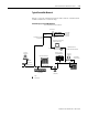
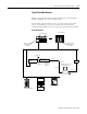
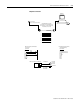
Table Of Contents
- 2706-UM017C-EN-P InView Communications User Manual
- Summary of Changes
- Table of Contents
- 1 - Introduction to InView Connectivity
- 2 - Install InView Communication Modules
- Mount Module to 2706-P42, 2706-P43 and 2706-P44 Displays
- Wire Communication Module to InView Display 2706-P42, 2706-P43, 2706-P44
- Mount Communication Kit to 2706-P72, 2706-P74, 2706-P92 and 2706-P94 Displays
- Wire Communication Kit to 2706-P72, 2706-P74, 2706-P92 and 2706-P94 Displays
- Use Communication Module with a 2706-P22R Display
- 3 - InView Communication Module Connections
- 4 - Application Guide
- ControlNet Communication and Tag Setup Screens
- DeviceNet Communication and Tag Setup Screens
- Data Highway Plus (DH+) Communication and Tag Setup Screens
- DH485 Communication and Tag Setup Screens
- EtherNet Communication and Tag Setup Screens
- RIO Communication and Tag Setup Screens
- Save or Download an Application File
- 5 - InView Communication Module Troubleshooting
- A - InView Communication Module Specifications
- Index
- Back Cover
Publication 2706-UM017C-EN-P - March 2006
InView Communication Module Connections 3-23
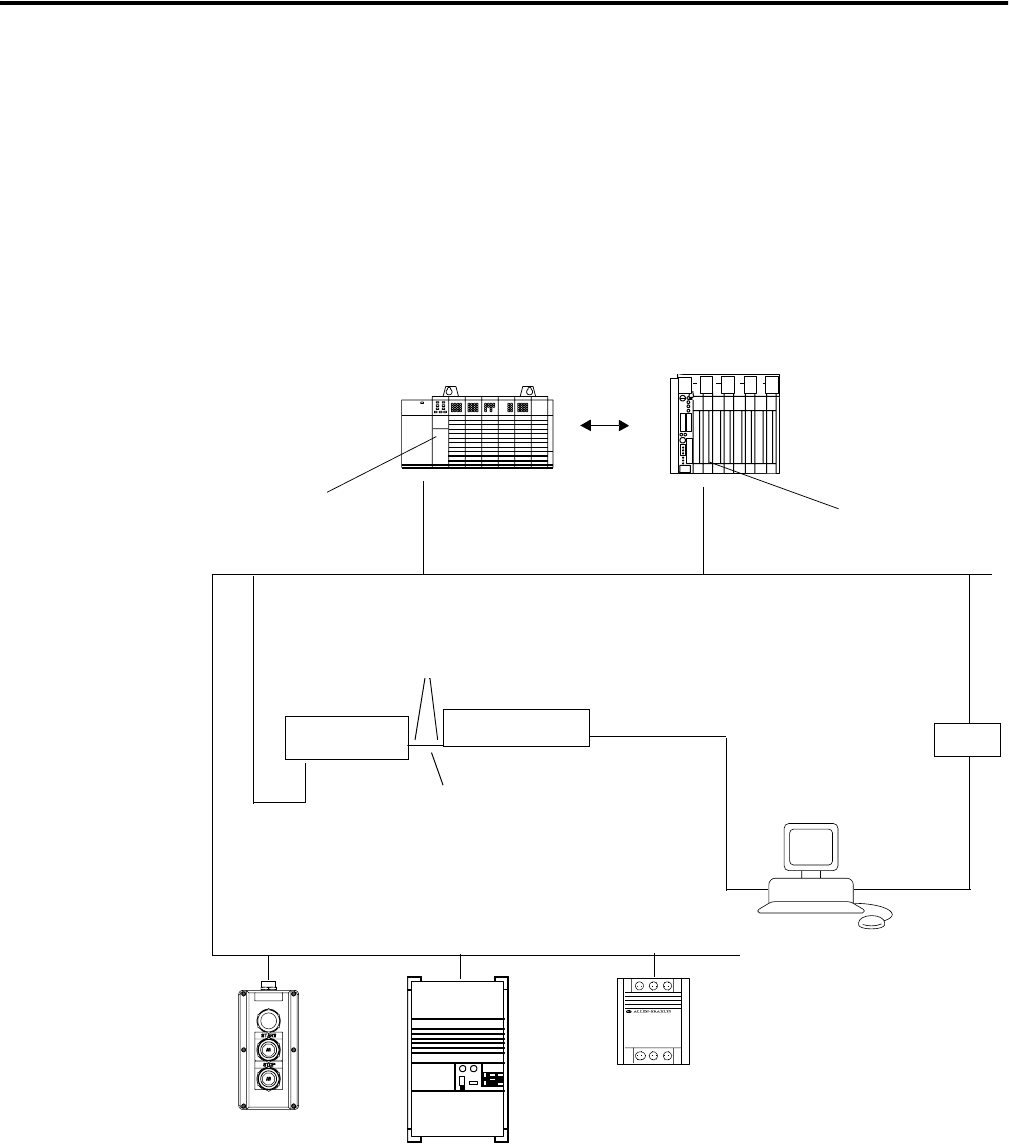
Typical DeviceNet Network
Below is a typical DeviceNet network with InView communication
modules installed on 2 of the network drops.
A DeviceNet network requires a 24V dc power supply. DeviceNet
power consumption is 24 mA to 90 mA at 24V dc. The InView
communication module does not receive its power from the network.
DeviceNet Network
or
SM
C
Download
1770-KFD
Module
Smart Motor Controller
SM
C
Drive
RediSTATION Module
DeviceNet Port
Serial Link
SLC 5/04 Controller
PLC-5 Controller
RS-232 Port
DeviceNet Scanner
Module (Cat. No.
1747-SDN)
DeviceNet Scanner
Module (Cat. No.
1771-SDN)
Computer for developing
InView applications
2706-P22R
2706-P4x
2706-P7x
2706-P9x
DNet Comm
Module
RS-232 Port
InView Display
Or
77156-094