
User Manual Manual
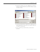
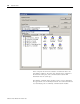
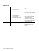
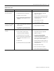
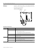

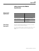

Table Of Contents
- 2706-UM017C-EN-P InView Communications User Manual
- Summary of Changes
- Table of Contents
- 1 - Introduction to InView Connectivity
- 2 - Install InView Communication Modules
- Mount Module to 2706-P42, 2706-P43 and 2706-P44 Displays
- Wire Communication Module to InView Display 2706-P42, 2706-P43, 2706-P44
- Mount Communication Kit to 2706-P72, 2706-P74, 2706-P92 and 2706-P94 Displays
- Wire Communication Kit to 2706-P72, 2706-P74, 2706-P92 and 2706-P94 Displays
- Use Communication Module with a 2706-P22R Display
- 3 - InView Communication Module Connections
- 4 - Application Guide
- ControlNet Communication and Tag Setup Screens
- DeviceNet Communication and Tag Setup Screens
- Data Highway Plus (DH+) Communication and Tag Setup Screens
- DH485 Communication and Tag Setup Screens
- EtherNet Communication and Tag Setup Screens
- RIO Communication and Tag Setup Screens
- Save or Download an Application File
- 5 - InView Communication Module Troubleshooting
- A - InView Communication Module Specifications
- Index
- Back Cover

Publication 2706-UM017C-EN-P - March 2006
InView Communication Module Troubleshooting 5-3
No communications with
MicroLogix, ControlLogix,
SLC or PLC controller.
1. Communications (COMM) fault.
2. Communication rates not set properly.
3. Controller is not in run mode.
4. InView communication module board node
and maximum node numbers are not set
correctly.
1. Check status of COMM LED.
Verify cable connections using cable
diagrams in Chapter 3.
2. Verify that InView communication module
board and controller are set at the same
communication rate.
3. Place controller in run mode.
4. Verify node address settings.
No communications with
PLC processor but COMM
LED indicator is active.
1. InView communication module board is
trying to communicate with a controller at a
different address.
2. The inhibit bit is set as the default on the
Channel Status Screen in the PLC processor.
1. Verify address of the controller.
2. Change setting of the inhibit bit.
No communications with
computer.
1. Communications (COMM) fault.
2. No SLC, network, or power supply
connection at terminal’s DH-485 port.
3. Communication rates not set correctly.
4. InView communication module board node
and maximum node numbers are not set
correctly.
5. Computer fault.
6. Communication driver not properly loaded.
1. Check status of COMM LED.
Verify cable connections using cable
diagrams in Chapter 3.
2. PIC receives power from DH-485
connection. Verify that the InView
communication module board is connected
to an SLC controller, network, or wallmount
power supply as shown in Chapter 3.
3. Verify that InView messaging software via
RSLinx and computer are set at the correct
communication rate.
4. Verify node number settings.
5. Refer to user manual for computer.
6. Refer to RSLinx online help or manual.
Troubleshooting Table
Problem Probable Cause(s) Corrective Action(s)