Installation Instructions InView Marquee Message Display Catalog Numbers 2706-P92C, 2706-P94C Topic Page Important User Information 2 Wiring and Safety Guidelines 3 Hazardous Location Considerations 4 Catalog Number Explanation 5 Mount the 2706-P92C and 2706-P94C Displays 6 Back-to-back Mounting 7 Connect the 2706-P92C and 2706-P94C Displays 8 Dip Switch Information 12 Additional Information 18 Legacy Communications Board Kit 13 Compact Flash Card 14 2706-P9x Temperature Protectio
InView Marquee Message Display Important User Information Solid state equipment has operational characteristics differing from those of electromechanical equipment. Safety Guidelines for the Application, Installation and Maintenance of Solid State Controls (Publication SGI-1.1 available from your local Rockwell Automation sales office or online at http://literature.rockwellautomation.com) describes some important differences between solid state equipment and hard-wired electromechanical devices.
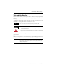
InView Marquee Message Display 3 Wiring and Safety Guidelines Install the InView display conforming to NFPA 70E, Electrical Safety Requirements for Employee Workplaces. In addition to the NFPA general guidelines, refer to the following: Careful cable routing helps minimize electrical noise. Route incoming power to the module by a separate path from the communication cables. TIP WARNING Do not run communications wiring and power wiring in the same conduit. SHOCK HAZARD • Maintain separation of circuits.
InView Marquee Message Display Hazardous Location Considerations This equipment is suitable for use in Class I, Division 2, Groups A, B, C and D or non-hazardous location only. The following WARNING statement applies to use in hazardous locations. The following information applies when operating this equipment in hazardous locations. Informations sur l’utilisation de cet équipement en environnements dangereux.
InView Marquee Message Display 5 Catalog Number Explanation 2706-P 9 2 C Bulletin Number 2706-P = InView Marquee Display Display Height (max character height) 9 = 9 in. (228.6 mm) max display character Display Length Large Marquee 2 = Short Case (appx. 0.91 m, 3 ft) with Std LED Pitch 4 = Long Case (appx. 1.
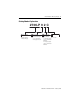
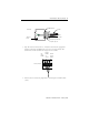
InView Marquee Message Display Mount the 2706-P92C and 2706-P94C Displays 1. Attach the two sign brackets to a wall, ceiling, or other surface. Be sure to place the brackets so the bracket flanges face appropriately as shown below. Mount the brackets the following distance apart (measured from the center of the mounting holes in each bracket): Mounted so flanges are hidden behind the sign. 2706-P92C:103.0 cm (40.55 in.) 2706-P94C: 194.4 cm (76.55 in.) Mounted so flanges show on the sides of the sign.
InView Marquee Message Display 7 3. Tilt the sign to select a viewing angle. To hold the sign in place, inset the remaining bolts into the desired viewing angle hole on each bracket. Ceiling Wall End View, Wall/Ceiling Mounted TIP Desired Viewing Angle Hole Keep a minimum 2.54 cm (1.0 in.) clearance on all sides of the sign for adequate ventilation. Back-to-back Mounting 1. Attach the brackets to the sign in the ceiling mount position. Use the hex bolts supplied.
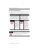
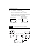
InView Marquee Message Display Connect the 2706-P92C and 2706-P94C Displays WARNING HAZARDOUS VOLTAGE • Contact with high voltage may cause death or serious injury. Always disconnect power to sign prior to servicing. • Maintain Separation of circuits. Route the incoming power directly to the power connection terminal block. • Do not run the power wiring over the logic board or optional Legacy Communication board. 1.
InView Marquee Message Display 9 Rubber Gasket Front View Conduit Connector, Outside End Sign Case, inside Connector nut, with teeth facing the sign case. 3. Strip the electrical wires back 1/4”. Insert the wires into the appropriate terminal connection and tighten the screw to 0.79 N•m (7 lb•in). The terminal block is UL rated for wire ranges of 14 to 8 AWG.
InView Marquee Message Display 5. Connect the incoming communication wires per the tables below. ATTENTION Use shielded Ethernet cable. Shielded Ethernet cable is required to maintain noise immunity. The 2706-P Cable1 is used for downloading messages only and must be removed after downloading is complete. TB2 is used for supplying power to the optional InView Legacy Communication board kit. Communication Openings Ethernet TB1 RJ-12 TB2 TB3 TB1 - RS-485 1.GND 4.CH A 2.SHLD 5.CH B 3.COMM 6.
InView Marquee Message Display 11 Ethernet (RJ-45)(1) (1) 1.TD+ 5.NC 2.TD- 6.RD- 3.RD+ 7.NC 4.NC 8.NC Use shielded Ethernet cable to maintain noise immunity. Download Port (RJ-12)(1) (1) 1.Aux +5V 4.RX 2.NC 5.NC 3.TX 6.GND The 2706-PCable1 is used for downloading messages only and must be removed after downloading is complete. 6. Carefully close the front of the sign case and turn the half-turn latches to the right with a large screwdriver.
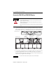
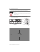
InView Marquee Message Display Dip Switch Information There are two dip switches located on the controller board, Switch 1 and Switch 2. Switch 2 Switch 1 Switch 1 Switch 1 is used to configure the display - RS485 echo enable, baud rate settings, and display size. • Position 1 enables or disables the echo function. Enabling the RS485 echo function allows any packets that come in on COM 0 (download, RJ-12 port), COM 1 (RS-232, TB3 port), and the Ethernet TCP/IP port to be sent out the RS485 port.
InView Marquee Message Display 13 Switch 2 Switch 2 is used to set the serial address of the display. Position 1 is the LSB of the address and position 8 is the MSB of the address. • If position 1 is on and all other positions are off, the display address will be 1. • If position 8 is on and all other positions are off, the display address will be 128. • If all positions are set to off, the serial address can be set using the InView Messaging software.
InView Marquee Message Display attached to the internal mounting plate. See publication 2706-IN015 for more information on how to install the board kit. PEM Spacers Compact Flash Card This product uses a Type I Compact Flash Card for message file storage. 2706-P9x Temperature Protection InView P92C and P94C signs have automatic temperature controls that help to protect the sign from damage when the internal temperature of the sign is too hot to continue normal operation.
InView Marquee Message Display TIP 15 Take into account the effects of ambient temperature when evaluating mounting locations for the sign. You should always maintain recommended clearance distances around the sign and avoid poorly ventilated mounting locations that could be subject to radiation, convection, conduction or other thermal transfer effects.
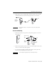
InView Marquee Message Display Follow these steps to replace the battery in the InView 2706-P92C or 2706-P94C message displays. 1. Disconnect power from the message display. 2. Turn the half-turn latches all the way to the left until they hit the stop. 3. Carefully lower the door. Front View, closed Front View, open Half-turn Latches on an 2706-P94C Sign Circuit Board 4. Locate the battery on the circuit board. Battery Press down here to pop battery out. 5.
InView Marquee Message Display 17 Specifications 2706-P92C 2706-P94C Display Display type LED matrix: Tri-Color (C) Display window size (W x H) 91.4 x 24.4 cm (36 x 9.6 in.) 182.9 x 24.4 cm (72 x 9.6 in.) Display array 120 x 32 pixels 240 x 32 pixels Center to center pixel spacing (pitch) 0.76 cm (0.3 in.) Number of lines 1…5 Lines of text/character height/ minimum characters per line 1 line/9.6 in./13(1) 1 line/9.6 in./26(2) 2 line/4.5 in./13(1) 2 line/4.5 in./26(2) 3 line/3.0 in.
InView Marquee Message Display Input Current Requirements for 2706-P92C and 2706-P94C Line Voltage (VAC) Frequency (Hz) 100% Display Load (Amp) 50% Display Load (Amp) 25% Display Load (Amp) 100 - P92C 50/60 3.6 2.1 1.3 100 - P94C 50/60 7.1 3.9 2.3 120 - P92C 50/60 2.9 1.7 1.0 120 - P94C 50/60 5.8 3.2 1.9 240 - P92C 50/60 1.4 0.9 0.6 240 - P94C 50/60 2.8 1.6 1.
InView Marquee Message Display 19 Notes: Publication 2706-IN016D-EN-P - February 2009
Rockwell Automation Support Rockwell Automation provides technical information on the Web to assist you in using its products. At http://support.rockwellautomation.com, you can find technical manuals, a knowledge base of FAQs, technical and application notes, sample code and links to software service packs, and a MySupport feature that you can customize to make the best use of these tools.