
User Manual Manual

Publication 2706-UM016D-EN-P - March 2006
InView Protocol 4-17
the result. The error check byte is done from the address up to the
data field.
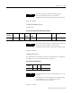
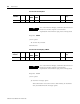
The following is an example of how to calculate the LRC in a Modbus
ASCII transmission.
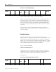
Example of LRC Calculations
Examples of Modbus ASCII
Functions
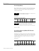
The following sections show examples of Modbus ASCII protocol
Query/Response transmissions to/from a display for each command
instruction listed above. Modbus ASCII will write/read to the holding
registers in the display. These registers are in the 40000 range. When
writing to register 40101, 40001 is dropped from the address leaving
100 (0x64). The following example shows the transmission of data to
holding register 40102 in all displays. The display adds 40001 to the
starting address upon receiving the transmission before updating the
appropriate holding register.
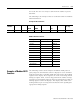
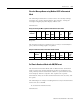
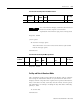
Beginning
of Frame
ADDR FUNC H.O.
ADDR
L.O.
ADDR
DATA LRC
Error
EOF Ready to
rec. resp
05 06 00 1F 0264 70 CR LF
Modbus ASCII Transmission
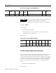
Message Transmitted Bytes Binary
Address 05 0000 0101
Function 06 0000 0110
Start Add H.O. 00 0000 0000
Start Add L.O. 1F 0001 1111
Data H.O. 02 0000 0010
Data L.O. 64 0110 0100
Sum 90 1001 0000
1's Complement 0110 1111
+1 +0000 0001
2's Complement 0111 0000
Transmitted as 70