
User Manual Manual

Publication 2706-UM016D-EN-P - March 2006
InView System Connectivity 2-3
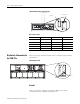
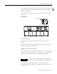
The 2706-P22R display has a ten-position dip switch. The first eight
positions are used to set the address of the display. Position nine is
used to put the display in diagnostic mode. Position ten is a spare.
The dip switch is read only on power-up.
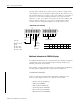
The diagnostic mode causes the display of LED patterns to visually
indicate if any pixels are not turning on. It also performs a memory
check.
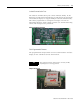
RJ11 Connections
Pin Pin Name Pin Pin Name
1. +5 V 4. RX
2. NC 5. NC
3. TX 6. GND
RS-485 Connections
Pin Pin Name Pin Pin Name
1. E-GND 4. CH A
2. SHLD 5. CH B
3. COMM 6. TERM
RS-232 Connection
Pin Pin Name Pin Pin Name
1. NC 6. NC
2. RX 7. RTS
3. TX 8. CTS
4. NC 9. NC
5. GND
IMPORTANT
After one complete LED scan is done, a RAM check
is performed and the display’s memory is cleared. To
ensure that the display’s memory is not cleared, turn
off power to the display after the LED block test is
performed. Make sure that the download or message
file has been saved before diagnostic test is allowed
to run completely through.