
User Manual Manual

Publication 2706-UM016D-EN-P - March 2006
Install InView Marquee Message Display 1-15
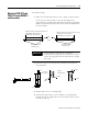
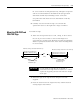
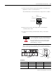
2. Feed electrical cable through 2.54 cm (1 in.) water-tight conduit,
the outside end of the connector (supplied), the electrical
opening in the sign case, and then through the inside end of the
connector.
3. Screw the inside and outside ends of the connector together
until water-tight.
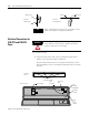
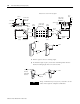
4. Strip the electrical wires back 6.35 cm (0.25 in.).
5. Connect the wires by screwing the end of each wire into the
power connection.
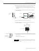
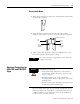
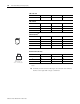
6. If the sign is to be used with serial communications, remove one
or both of the hole plugs from the lowest holes on the right end
of the sign case.
Otherwise, proceed to Step 7.
Right-end
view
Electrical opening
Front view
Sign case,
inside
Conduit
Connector,
outside end
Connector nut, with teeth
facing the sign case
Rubber gasket
Power connection
LINE 1
GROUND
LINE 2 OR
NEUTRAL
LINE 1
GROUND
LINE 2 OR
NEUTRAL
208 - 240 VAC INPUT
Neutral
(Line 2):
WHITE
Line
(Hot)
BLACK
Ground
GREEN
w/
Yellow
Serial device hole
plug/opening
Right-end view
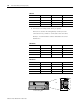
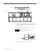
TIP
TB1 can be used for incoming serial connection for
RS-232 or RS-485. The full pinout diagram is shown
below.