
User Manual Manual

Publication 2706-UM016D-EN-P - March 2006
Install InView Marquee Message Display 1-5
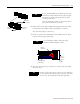
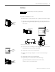
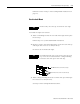
TB1 can be used for incoming RS-232 or RS-485 serial
connection. They cannot be connected at the same time. RS-485
is recommended to reduce undesirable electrical interference.
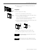
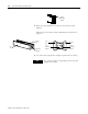
7. P1 can be used for incoming RS-232 only, although it is optional
and not recommended.
P1 is intended for RS-232 application downloads and RS-485
terminating resistor connection.
See publication 2706-IN007 for more information on RS-485
termination.
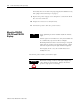
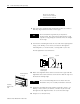
8. To maintain NEMA compliance and to prevent EMI emissions,
install hole plugs in any open conduit holes in the power supply
enclosure.
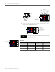
TB1
Incoming serial
wires
8
7
6
5
4
3
2
1
TIP
Be sure to place the wires so they are not caught by
screws when replacing the power supply cover, and
also so they do not interfere with fan operation.
TB1 - RS-232
Pin Pin Name Pin Pin Name
1. GND 5. NC
2. NC 6. NC
3. RS-232 TX 7. NC
4. RS-232 RX 8. NC
TB1 - RS-485
Pin Pin Name Pin Pin Name
1. NC 5. RS-485(+)
2. NC 6. RS-485(-)
3. NC 7. NC
4. NC 8. SHIELD
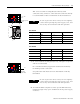
P1
Incoming
serial wires
TIP
Be sure to place the wires so they are not caught by
screws when replacing the power supply cover, and
also so they do not interfere with fan operation.