InView Marquee Message Display 2706-P22R, 2706-P42, 2706-P43, 2706-P44, 2706-P72, 2706-P74, 2706-P92, 2706-P94 User Manual
Important User Information Solid state equipment has operational characteristics differing from those of electromechanical equipment. Safety Guidelines for the Application, Installation and Maintenance of Solid State Controls (publication SGI-1.1 available from your local Rockwell Automation sales office or online at http://literature.rockwellautomation.com) describes some important differences between solid state equipment and hard-wired electromechanical devices.
Summary of Changes This document describes the InView Marquee Message Display. Revision bars in the margin identify updated information. Changes for this version of the document include: Change 1 Page Updated information on how to change the serial address 1-2 Added information about how to use the 2706-PCABLE1 to download a message application 1-27 Added information about the communication module when you set the IP address.
2 Summary of Changes Publication 2706-UM016D-EN-P - March 2006
Table of Contents Chapter 1 Install InView Marquee Message Display Introduction . . . . . . . . . . . . . . . . . . . . . . . . . . . . . . . . . . . Wire and Safety Guidelines . . . . . . . . . . . . . . . . . . . . . . . . Change the Serial Address . . . . . . . . . . . . . . . . . . . . . . . . . Checkout Procedure . . . . . . . . . . . . . . . . . . . . . . . . . . . . . Electrical Connections for 2706-P42, 2706-P43 and 2706-P44 Displays . . . . . . . . . . . . . . . . . . . . . . . . . . . . . . .
ii Table of Contents Gateway Address and Subnet Mask Setup . Create the Message File . . . . . . . . . . . . . . . . . Attach a Note to a Message . . . . . . . . . . . Text Color . . . . . . . . . . . . . . . . . . . . . . . . Date, Time and Variables . . . . . . . . . . . . . Category . . . . . . . . . . . . . . . . . . . . . . . . . Message Priorities . . . . . . . . . . . . . . . . . . Pause . . . . . . . . . . . . . . . . . . . . . . . . . . . Message Header. . . . . . . . . . . . . . . . . . . .
Table of Contents iii Mode of Transmission . . . . . . . . . . . . . . . . . . . . . . . . . InView Display Memory Map . . . . . . . . . . . . . . . . . . . . Methods of Transmission . . . . . . . . . . . . . . . . . . . . . . . Message Format . . . . . . . . . . . . . . . . . . . . . . . . . . . . . . Longitudinal Redundancy Check (LRC) Error Detection and Calculation . . . . . . . . . . . . . . . . . . . . . . Examples of Modbus ASCII Functions . . . . . . . . . . . . . . . . Heartbeat Function . . . .
iv Table of Contents Chapter 5 InView Control and InView Control API Introduction . . . . Quick Overview . Reference . . . . . . Properties . . . . . . Methods . . . . . . . . . . . . . . . . . . . . . . . . . . . . . . . . . . . . . . . . . . . . . . . . . . . . . . . . . . . . . . . . . . . . . . . . . . . . . . . . . . . . . . . . . . . . . . . . . . . . . . . . . . . . . . . . . . . . . . . . . . . . . . . . . . . . . . . . . . . . . . . . . . . . . . . . . . . . . . .
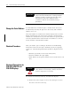
Chapter 1 Install InView Marquee Message Display Introduction These instructions show how to change the serial address and how to mount InView series signs with NEMA Types 4, 4X, and 12 enclosures. These signs are intended for indoor use only. Type 4 enclosures are intended to provide a degree of protection against windblown dust and rain, splashing water, and hose-directed water.
1-2 Install InView Marquee Message Display IMPORTANT Change the Serial Address Power wiring must be in accordance with Class I, Class II and Class III Division 2 wiring methods (Articles 501-4(b), 502-4(b) and 503-3(b) of the National Electrical Code, NFPA70) and in accordance with the local authority having jurisdiction. A serial address for an InView sign is a number from 1 to 254 in hexadecimal (01 to FE). All signs leave the factory with a default address of 1 or 01.
Install InView Marquee Message Display It is recommended that you install power and serial wires at the bottom of the power supply enclosure to reduce noise from power wires crossing serial wires. TIP Hole plugs, top, removed Hole plugs, bottom, removed Wing nuts for hole plugs 1-3 You can install the power or serial wires at the top of the enclosure if necessary. 2. Remove the left or right conduit hole plug from the top of the enclosure by removing its wing nut inside the enclosure.
1-4 Install InView Marquee Message Display Line (Hot) BLACK Ground GREEN w/ Yellow Neutral (Line 2): WHITE Hot (Line 1) H N Ground Neutral (Line 2) 100 to 240V ac @ 50/60 Hz 5. Insert the serial wires through the right conduit hole on either the top or the bottom of the sign. Insert the serial wires into one of these conduit holes. TIP TB1 TB1 can be used for incoming serial connection for RS-232 or RS-485. TB1 - Full Pin Pin Name Pin Pin Name 1. GND 5. RS-485(+) 2. +5V 6.
Install InView Marquee Message Display TB1 can be used for incoming RS-232 or RS-485 serial connection. They cannot be connected at the same time. RS-485 is recommended to reduce undesirable electrical interference. TB1 Incoming serial wires 8 7 6 5 4 3 2 1 1-5 TIP Be sure to place the wires so they are not caught by screws when replacing the power supply cover, and also so they do not interfere with fan operation. TB1 - RS-232 Pin Pin Name Pin Pin Name 1. GND 5. NC 2. NC 6. NC 3.
1-6 Install InView Marquee Message Display If needed, there is an extra hole plug supplied in addition to any hole plugs removed in Step 2 on page 3. 9. Replace the power supply cover using the 6 screws from when the cover was removed. 10. Torque the screws to 2.7 Nm (24 lb-in). 11. Connect the power cable to a power source. Mount the 2706-P42, 2706-P43 and 2706-P44 Displays TIP Only qualified personnel should install the InView signs.
Install InView Marquee Message Display 1-7 Wall Mount Remove only one end cap at a time. TIP To mount the display to a wall: 1. Remove the 4 screws and the end cap from one end of the sign. Remove these screws. 2. Slide one of the wall mounting brackets onto the back of the sign until it is approximately 13 mm (0.5 in.) away from the end of the sign. 0.5” Wall mounting bracket Wall mounting bracket 33.13 (1.30) 25.40 (1.00) 12.70 (0.50) 7.62 (0.30) 127 (5.00) 33.13 (1.305) 17.65 (0.70) 2.65 (0.
1-8 Install InView Marquee Message Display 94 cm (37 in.) for 2706-P42 183 cm (72.2 in.) for 2706-P43 185.4 cm (73 in.) for 2706-P44 8. Attach the two remaining wall mounting brackets to a wall so that they align with the brackets on the sign. TIP Do not install the sign directly to drywall or plaster-board. The sign must be fastened to a wall capable of supporting at least four times the weight of the sign. 9.
Install InView Marquee Message Display 1-9 13. Torque the 5/16 nuts in the mounting holes (See Step 9) to 2.7 Nm (24 lb-in). Lock nuts Washers Ceiling Mount Phillips screws To mount the display to the ceiling: 1. Remove one screw from the top of the end cap. Remove this screw. 2. Line up a ceiling bracket with the top hole on the sign’s end cap so the bracket fits in the indentation. There are left and right ceiling brackets. Use the one that fits with the screw hole’s countersunk side facing out. 3.
1-10 Install InView Marquee Message Display Stack Mount TIP WARNING Stacking bracket Screw Up to 4 signs can be hung together vertically (‘stacked’). Mounting system for stack mounting must support a minimum of four times the total weight of all signs being stacked. Possible crush hazard. Do not stack more than 4 signs. Otherwise signs may fall causing serious injury or death. To stack the signs: 1. Remove the top screw from each end cap of the bottom sign 2.
Install InView Marquee Message Display 1-11 Follow the notes in Step 4 of the Ceiling Mount instructions on page 1-9. Back-to-back Mount TIP Remove only one end cap at a time for each sign. To mount the signs back-to-back: 1. Attach a mounting bracket on each end of the signs and replace the end caps. Follow Steps 1 to 5 of the Wall Mount instructions. 2. However, replace only the bottom three screws for each end cap and torque the screws to 2.7 Nm (24 lb-in). Do this for each end of both signs.
1-12 Install InView Marquee Message Display Ceiling mounting bracket 4. Match the signs together back-to-back and connect them together. Follow Steps 7 through 10 of the Wall Mount instructions on page 1-8. Second sign First sign Mounting brackets First sign Second sign First mounting bracket Second mounting bracket 5. Use chains (not supplied) to hang the signs from the ceiling.
Install InView Marquee Message Display Mount the 2706-P72 and 2706-P74 series NEMA 4 and 4x models 1-13 To mount the sign: 1. Attach the two sign brackets to a wall, ceiling, or other surface. Be sure to place the brackets so the bracket flanges face appropriately as shown below. Mount the brackets the following distance apart (measured from the center of the mounting holes in each bracket): Mounted so flanges are hidden behind the sign 2706-P72CNx: 104.8 cm (41.25 in.) 2706-P74CNx: 165.8 cm (65.25 in.
1-14 Install InView Marquee Message Display Ceiling Phillips screw End view, wall-mounted Phillips screw End view, ceiling-mounted Wall Keep a minimum 2.54 cm (1.0 in.) clearance on all sides of the sign for adequate ventilation. TIP Electrical Connections for 2706-P72 and 2706-P74 Signs Hazardous voltage. Contact with high voltage may cause death or serious injury. Always disconnect power to sign prior to servicing. WARNING To connect the sign: 1.
Install InView Marquee Message Display 1-15 2. Feed electrical cable through 2.54 cm (1 in.) water-tight conduit, the outside end of the connector (supplied), the electrical opening in the sign case, and then through the inside end of the connector. 3. Screw the inside and outside ends of the connector together until water-tight. Rubber gasket Front view Right-end view Electrical opening Conduit Connector, outside end Sign case, inside Connector nut, with teeth facing the sign case 4.
1-16 Install InView Marquee Message Display TB1 Full Pin Pin Name Pin Pin Name 1. GND 5. RS-485(+) 2. +5V 6. RS-485(-) 3. RS-232 TX 7. NC 4. RS-232 RX 8. SHIELD 7. Connect the incoming serial wires per pinout. TB1 can be used for incoming RS-485 or RS-232 serial connection. They cannot be connected at the same time. RS-485 is recommended to reduce undesirable electrical interference. TB1 RS-485 Pin Pin Name Pin Pin Name 1. NC 5. RS-485(+) 2. NC 6. RS-485(-) 3. NC 7.
Install InView Marquee Message Display 1-17 P1 can be used for incoming RS-232 only, although it is optional and not recommended.P1 is intended for RS-232 application downloads and RS-485 terminating resistor connection. See publication 2706-IN007 for more information on RS-485 termination. 8. Carefully close the front of the sign case and turn the quarter-turn latches to the right with a large screwdriver. Mount the 2706-P92C and 2706-P94C Sign To mount the sign: 1.
1-18 Install InView Marquee Message Display Dimensions are shown in mm (in.) approx. 139.16 (5.40) 10.16 (.40) 33.78 (1.33) 22.35 (.88) 8.74 x 17.48 (.344 x .688) OBROUND 8.74 x 17.48 (.344 x .688) OBROUND 0.572 (14.53) 14.53 (0.572) 44.45 44.45 (1.75) (1.75) Ø 7.14 (.281) 10° 8.74 x 17.48 (.344 x .688) OBROUND 14.53 (0.572) 117.60 (4.63) Ø 7.14 (.281) 117.60 (4.63) 38.10 (1.50) Left Bracket 33.78 (1.33) 22.35 (.88) 10° Ø 7.14 (.281) 19.30(.76) 10.16(.40) 10.16(.40) 3.43 (.135) 44.
Install InView Marquee Message Display 1-19 Back-to-back Mount 1. Attach the brackets to the sign in the ceiling mount position with the hex bolts supplied. 2. Match the signs together back-to-back and connect them together using a total of six 5/16” bolts and nuts (not supplied). Attach chains here First sign Second sign Second mounting bracket First mounting bracket 3. Attach chains (not supplied) to the top mounting holes of the bracket to hang the signs from the ceiling.
1-20 Install InView Marquee Message Display Front view, closed Half-turn latches on an 2706-P94C sign Front view, open Electrical opening Power connection terminal block Communication opening 4. Feed electrical cable through 12.7 mm (0.5 in.) water-tight conduit, the outside end of the connector (supplied), the electrical opening in the sign case, and then through the inside end of the connector. 5. Screw the inside and outside ends of the connector together until water-tight.
Install InView Marquee Message Display 1-21 7. Insert the wires into the appropriate terminal connection and tighten the screw to 0.79 Nm (7 lb-in). The terminal block is UL rated for wire ranges of 14 to 8 AWG. Line (Hot) BLACK Ground GREEN w/ Yellow Neutral (Line 2): WHITE LINE 1 GROUND LINE 2 OR NEUTRAL LINE 1 GROUND LINE 2 OR NEUTRAL Power connection 208 - 240 VAC INPUT 8. Remove the necessary hole plugs before connecting the communications cables. 9.
1-22 Install InView Marquee Message Display TB2 - Aux +5V Pin Pin Name 1. Pin +5V Pin Name 2. GND TB3 - RS-232 Pin Pin Name Pin Pin Name 1. TXD 4. CTS 2. RXD 5. GND 3. RTS 6. EGND Ethernet (RJ-45)(1) Pin 1 8 (1) Pin Name Pin Pin Name 1. TD+ 5. NC 2. TD- 6. RD- 3. RD+ 7. NC 4. NC 8. NC Use shielded Ethernet cable to maintain noise immunity. Download Port (RJ-12)(1) RJ12 Pin 1 2 3 4 5 6 +5V NC TX RX NC GND (1) Pin Name Pin Pin Name 1. Aux +5V 4. RX 2.
Install InView Marquee Message Display Mount the 2706-P22R Display 1-23 The following provides panel cutout dimensions and overall dimensions for the InView P22R panel mount display. The InView P22R mounts in a custom panel or enclosure. When it is properly installed, the faceplate provides a NEMA Type 12, 13, and 4X(indoor) rating. To mount the display: 1. Cut and drill the appropriate mounting holes in the enclosure or panel. Refer to Panel Cutout Dimensions for 2706-P22R Display on page 1-23 2.
1-24 Install InView Marquee Message Display Dimensions for 2706-P22R Display 337.3 (13.29) 111.3 (4.38) 365.0 (14.357) 83.8 (3.30) All dimensions are in millimeters (inches) 61.7 (2.43) Electrical Connections for 2706-P22R Display 68.8 (2.71) with fuse The InView display requires 18 to 30V dc, 0.5 A at 18V dc. ATTENTION Before making power connections, make sure that the power is turned off. Improper wiring of the power connections may result in personal injury or damage to the InView display.
Install InView Marquee Message Display Communication Connections for 2706-P22R Display 1-25 RJ12 6 - TERM 1 - E-GND 2 - SHLD 3 - COMM 4 - CH A 5 - CH B RS-485 1 2 3 4 5 6 +5V NC TX RX NC GND RS-232 1 2 6 3 7 4 8 5 9 RJ11 Connections Pin Pin Name Pin Pin Name 1. +5 V 4. RX 2. NC 5. NC 3. TX 6. GND RS-485 Connections Pin Pin Name Pin Pin Name 1. E-GND 4. CH A 2. SHLD 5. CH B 3. COMM 6. TERM RS-232 Connection Pin Pin Name Pin Pin Name 1. NC 6. NC 2. RX 7.
1-26 Install InView Marquee Message Display DIP Switch Settings for 2706-P22R Display Switch Settings 1 1 2 2 3 4 4 8 5 16 6 32 7 64 8 128 Dip Switches Dip Switch Label LSB Serial Address MSB Diagnostics Not Used ATTENTION Disconnect power from the InView display before setting any switch. Switch settings are scanned only on power-up. Dip Switch Settings Switch Publication 2706-UM016D-EN-P - March 2006 Switch Setting Switch Switch Setting 1. 1 (LSB) 6. 32 2. 2 7. 64 3. 4 8.
Install InView Marquee Message Display Download a Message Application 1-27 InView message applications are created using the InView messaging software (2706-PSW1). After creating the Message Application, you need to download it into your InView display memory. InView applications can be downloaded using: • Point-to-point serial communications (RS-232) from the communication port on a personal computer. • Multi-drop RS-485 serial communications.
1-28 Install InView Marquee Message Display RS-485 Echo The RS-485 echo feature addresses the issue of increased network traffic often caused by multiple node addresses and high consumption of communication bandwidth. The display’s design enables users to daisy-chain numerous InView displays off an InView P9x via the RS-485 communication network. 2706-P9x - Master InView RS-485 Network In order to set the 2706-P92C display or the 2706-P94C display as a Master, the echo dip switch must be enabled.
Install InView Marquee Message Display 1-29 Global Addressing The 2706-P92C and 2706-P94C displays can both set their serial address to 255, which is the global (broadcast) address. A display with the serial address of 255, accepts all message packets regardless of the address actually given in the packet. This allows the user to route all messages to the 2706-P9x InView display. See Dip Switch Information for the 2706-P9x in Chapter 2, for serial address configuration.
1-30 Install InView Marquee Message Display Network Wiring RJ11 RJ11 8 SHLD 6 6 Term Term Term A AUX B(-) B(-) B RS485(-) A(+) A(+) COM RS485(+) COM COM 6 8 RxD SHLD GND 1 SHLD SHLD TxD E-GND E-GND +5V 1 1 GND 1 1 1761-NET-AIC 2706-P74C 2706-P44C 2706-P9x 2706-P22R End-Of-Line Display TIP Publication 2706-UM016D-EN-P - March 2006 End-of-line InView display should have terminating resistor in RJ11 (P1).
Chapter 2 InView System Connectivity This chapter demonstrates how the InView display connects to control networks. In the following chapters we show controller configuration and sample ladder for serial ASCII networks. This chapter also discusses how to set-up the display attributes, communications and create messages. Serial ASCII Communications Refer to Chapter 3 for more information on Serial ASCII communications from Channel Zero of an Allen-Bradley controller.
2-2 InView System Connectivity These displays have a single channel UART and therefore can only have one of the three communication options connected at a time. TB1 Connections • RJ-12 • RS-232 terminal block connections • RS-485 terminal block connections TB1 Incoming serial wires TB1 - Full 8 7 6 5 4 3 2 1 Pin Pin Name Pin Pin Name 1. GND 5. GND RS-485(+) 2. +5V 5. +5V RS-485(-) 3. RS-232 TX 6. RS-232 TX NC 4. RS-232 RX 7.
InView System Connectivity 2-3 RJ11 Connections Pin Pin Name Pin Pin Name 1. +5 V 4. RX 2. NC 5. NC 3. TX 6. GND RS-485 Connections Pin Pin Name Pin Pin Name 1. E-GND 4. CH A 2. SHLD 5. CH B 3. COMM 6. TERM RS-232 Connection Pin Pin Name Pin Pin Name 1. NC 6. NC 2. RX 7. RTS 3. TX 8. CTS 4. NC 9. NC 5. GND The 2706-P22R display has a ten-position dip switch. The first eight positions are used to set the address of the display.
2-4 InView System Connectivity 2706-P22R Display Dip Switch Settings Switch Settings 1 1 2 2 3 4 4 8 5 16 6 32 7 64 8 128 Dip Switch Label Dip Switches LSB Serial Address MSB Diagnostics Not Used Dip Switch Settings Switch Dip Switch Information for the 2706-P9x Switch Setting Switch Switch Setting 1. 1 (LSB) 6. 32 2. 2 7. 64 3. 4 8. 128 (MSB) 4. 8 9. Diagnostics 5. 16 10. Not Used There are two dip switches located on the controller board, Switch 1 and Switch 2.
InView System Connectivity 2-5 Position 1 enables or disables the echo function. When you enable the RS485 echo function, this allows any packets that come in on COM 0 (download, RJ-12 port), COM 1 (RS-232, TB3 port), and the Ethernet TCP/IP port to be sent out the RS485 port. This allows Ethernet TCP/IP and other communication protocols to be converted to RS485 by a single 2706-P92 or 2706-P94 and then sent out to multiple RS485 networked displays.
2-6 InView System Connectivity The dip switch setting takes priority over the software setting. If the serial address is set to 2 using the software (all the dip switches set to off) and then Switch 2 is used to set the serial address to 3 (position 1 and 2 set to on and the remaining positions set to off), the serial address is 3.
InView System Connectivity 2-7 The Communications Board Kits convert the six protocols to RS-232. The board kit mounts on the four PEM spacers that are attached to the internal mounting plate. See publication 2706-IN015 for more information on how to install the board kits. Spacer Location PEM Spacers Compact Flash Card This product uses a Type I Compact Flash Card for message file storage. Refer to publication 2706-IN017 for information on replacement and installation of the Compact Flash Card.
2-8 InView System Connectivity To set the communication rate using the messaging software: 1. Highlight the 2706-P9x display you wish to set the communication rate. 2. Select Set Display Baud Rate under the Tools menu. 3. Choose the communication rate you wish to set the display at and click on the Set button. TIP Publication 2706-UM016D-EN-P - March 2006 There is no confirmation that the command was sent. The display must be power cycled to view the new communication rate settings.
InView System Connectivity 2-9 Isolated Communication Ports The isolated communication ports consist of RS-232, RS485, 10/100 Ethernet port and a RS-232 download port. This allows the 2706-P92C and 2706-P94C displays to support multiple networks simultaneously. This allows programmers to change the messages or tie into an information database, while control operators can continue delivering alarms and messages to the plant floor.
2-10 InView System Connectivity Power-up Messages After the power cable and the download cable (attaches to the RJ-12 port) have been attached per the installation document, apply power to the display. TIP If a display is connected to Ethernet via TCP/IP by using a 2706-PENET1 module or a 2706-P9x display is connected to Ethernet via TCP/IP, the display configuration and message download can be done over Ethernet. For more information on this communication option, see publication 2706-IN008.
InView System Connectivity Display Setup 2-11 To set up your display: 1. Start the InView messaging software. 2. Create a project. The software prompts for a project file name, a project name, and description. Once this is done, the project name and description appears in the Displays box. 3. The software then prompts for a display name, display description, display type, and the number of that particular display that is used in the system (1 to 100 of the same display type). 4.
2-12 InView System Connectivity The 2706-PENET1 module is the communication interface for Ethernet TCP/IP. This module is used with the 2706-P22, 2706-P4x, and 2706-P7x displays. The 2706-P9x displays have this protocol built in. Note that the 2706-PENET1 is Ethernet TCP/IP or Office type Ethernet and is not Ethernet I/P, which is Ethernet Industrial Protocol available on Rockwell Automation logic controllers. To set the IP address: 1. Select the display you created, which use a the Ethernet module. 2.
InView System Connectivity 2-13 Under the section with the heading TCP/IP settings is the Configure Communications button. 4. By clicking this button you are taken to the Ethernet TCP/IP Communications window. This is where the IP address will be set. 5. At the top of the window labeled IP Address, enter the desired IP address.
2-14 InView System Connectivity 6. Enter 3001 for the Port if using a 2706-PENET1 module. 7. Enter the MAC Address of the module under the heading Assign IP Address. The MAC Address is found on the module itself. TIP The 2706-P9x display does not use MAC Address. IP Address changes must be done serially. 8. Click the Setup button located in the section titled Assign IP Address once the desired IP Address, Port, and MAC Address have been entered.
InView System Connectivity 2-15 Gateway Address and Subnet Mask Setup Set up the Gateway address and Subnet Mask if needed based on your Ethernet Network configuration. Default values typically are for Subnet Mask, 255.255.255.0 and as a default the Gateway address is left blank. Subnet Mask is a parameter that interprets IP addresses when the network is divided into multiple networks. The IP address is formatted as four sets of decimal numbers with periods between them (255.255.255.1).
2-16 InView System Connectivity After the IP Address, Gateway Address and Subnet Mask have all been established, click the OK button on the bottom of the Ethernet TCP/IP Communications window. This allows the settings to be saved and configuration is now complete. Once the settings have been saved, they can now be viewed by clicking on the Advanced button located in the section titled TCP/IP settings on the Edit Display window.
InView System Connectivity 2-17 Message File Additional Information Task Page Pause 2-19 Message Header 2-19 Preview Messages 2-19 Set the Display Address 2-19 Download Messages 2-20 Clear Memory/Message Queue 2-22 Attach a Note to a Message Select a message from the message list. Select Tools and Edit Note. Then a Message X Note window appears. The X is the message number for the message that a note is being created for.
2-18 InView System Connectivity InView configuration window (the project window) under Tools and Set Display Date and Time. Note that the time format is set for each display individually by address. The default format is standard. The data and time is also set here. Category The Category option is used to assign categories to messages. This helps in organizing messages for certain operations and when performing a find.
InView System Connectivity 2-19 Pause The Pause option determines how long a message is displayed when a message queue (two or more messages are being displayed due to a download and display or messages were added to a message queue) is running. See InView Protocol, Chapter 4, for information on how to messages to the message queue. Message Header A header is added to a message by clicking the H button.
2-20 InView System Connectivity eight dip switch positions are on, this is the display address and the software setting is overwritten. Once an address is selected by the dip switches, it is retained until it is overwritten by the software (only done when all switches are off) or the dip switches are changed. Once a unique address has been set, future display properties and message communications are done to networked signs via RS-485.
InView System Connectivity 2-21 file end remains. For example, the old message file had messages 1 through 10 and a background message. The new message file has messages 1 through 2 and a background message. After the new message file is downloaded, the new message file contains new messages 1 through 2, a new background message, and old messages 3 through 10. If the new message file does not contain a background message, the background message is blank.
2-22 InView System Connectivity Clear Memory/Message Queue These options are found under Tools then Clear Display Memory and Clear Display Message Queue. The clear memory option erases the entire memory of the display. Memory Cleared is displayed and then the display goes through a reset cycle. The clear message queue option just erases the queue, not the display memory. If there is a background message, it is displayed after a clear message queue command has been issued.
Chapter 3 Serial ASCII Communications Use a PLC5 out Channel Zero To use a PLC5 out Channel Zero on a display: 1. Create a new application. 2. Set up the channel configuration. 3. Create a file type String (ST). This is where the user inserts the ASCII/Hex commands. 4. Set up the ladder logic.
3-2 Serial ASCII Communications Use an SLC 5/03, 5/04, or 5/05 out Channel Zero The SLC processor is set up very similar to the PLC processor. The SLC processor uses the same ladder logic as the PLC processor shown below. To use an SLC processor out Channel Zero on a display: 1. Create the new application and then set up the channel configuration as shown. B3:0 0 0 1 AWT ASCII Write Channel 0 Source ST9:0 Control R6:0 String Length 0< Characters Sent 0< EN DN ER (End) 2.
Serial ASCII Communications Use a MicroLogix out Channel Zero or One 3-3 The MicroLogix processor is set-up similar to the SLC processor. They both use RSLogix500 software to communicate, however the channel configuration and ladder is slightly different. With the MicroLogix processor, the user can download with either channel 0 or 1 and can also write ASCII using channel 0 or 1. In this example the ASCII is done using channel 1.
3-4 Serial ASCII Communications Use ControlLogix Processor out Channel Zero To use a ControlLogix processor out Channel Zero on a display: 1. Open a new application. 2. Set up the controller properties by right-clicking on the controller name and selecting properties and then the serial port tab as follows: 3. Set up ladder logic and controller tags. toggle.0 0 AWT ASCII Write Channel Source 0 message [ 0 ] 0 SerialPort Control message_send String Length 0 Characters Sent 0 4.
Serial ASCII Communications Use the CompactLogix Processor out Channel Zero or One 3-5 To use a CompactLogix processor out Channel Zero on a display: 1. Open a new application. 2. Set up the controller properties by right-clicking on the controller name and selecting properties and then the serial port tab. The ladder is the same as a ControlLogix except that the user can select either channel zero or one. toggle.
3-6 Serial ASCII Communications Use FlexLogix Processor out Channel Zero To use a FlexLogix processor out Channel Zero on a display: 1. Open a new application. 2. Set up the controller properties by right-clicking on the controller name and selecting properties and then the serial port tab. 3. Set up ladder logic and controller tags. toggle.0 0 AWT ASCII Write Channel Source 0 message [ 0 ] 0 SerialPort Control message_send String Length 0 Characters Sent 0 4.
Chapter 4 InView Protocol Introduction The purpose of this chapter is to show the protocol that is required to trigger messages and update variables on InView displays with the InView protocol. In general, messages are downloaded through the software and stored within the display memory. Up to 4000 messages and 100 (0 to 99) variables can be created with the InView software. Messages are displayed using the Control-T function or Modbus ASCII. One of three different methods can be used.
4-2 InView Protocol Format shows the format for the Control-T function and Control-T Frame Description shows the acceptable values. Control-T Frame Format Optional(1) Name (1) [CTRL][T] MSG# Backslash Function Backslash Display Address If not used; the message will be shown as a Priority Message on all displays. When using a function, a display address must be included, even if it is a broadcast address of 255.
InView Protocol 4-3 all messages are removed or cleared, the background message (message # 4095) is displayed. TIP If no background message is programmed, the default message NO BACKGROUND MESSAGE appears. The CTRL-V Function Frame - Numeric Variables The CTRL-V function is used to update variables that are embedded within messages. The value of the variable number determines which variable register is updated in the display. If no display address is used, it updates all displays with the variable data.
4-4 InView Protocol TIP To send floating point numbers, you need to use 2 variables; one for the integer portion, and one for the decimal portion. i.e {var1;}.{var2;}. The CTRL-V Function Frame - Alphanumeric Variables The Ctrl-V Function is used to update variables that are embedded within messages. The value of the variable number determines which register to update in the message display. If no variable number is used, only variable 0 is updated.
InView Protocol 4-5 Flash Variable Data You can enable/disable flashing for the variable data by using [Ctrl] G1 to turn the variable on and [Ctrl] G0 to turn the variable off. For example, to flash the word text in the variable data how to flash text, you must enter the variable data as: how to flash [Ctrl]G[1]text[Ctrl]G[0] Change Color of Variable Data To change the color of variable data, you must add the following characters to the variable data for the specific color.
4-6 InView Protocol Name [CTRL][T] MSG # Backslash Display address Return ASCII ^T 45 \ 255 ^M Hex \14 \34\35 \5C \32\35\35 \0D Or Name [CTRL][T] MSG # Backslash Function Backslash Display address Return ASCII ^T 45 \ 1 \ 255 ^M Hex \14 \34\35 \5C \31 \5C \32\35\35 \0D TIP Allen-Bradley PLC processors requires two backslashes (\\) to be used as a delimiter. Other PLC manufactures may only require one backslash (\).
InView Protocol 4-7 Add a Message on all Displays This is an example of how to add message 2011 to all displays. Add a Message on all Displays Name [CTRL][T] MSG # Backslash Function Backslash Display address Return ASCII ^T 2011 \ 2 \ 255 ^M Hex \14 \32\30\31\31 \5C \32 \5C \32\35\35 \0D Adding a Message on a Specific Display The following adds message 348 to display address 055.
4-8 InView Protocol Or Name [CTRL][T] MSG # Backslash Display address Return ASCII ^T 4095 \ 255 ^M Hex \14 \34\30\39\35 \5C \32\35\35 \0D Or Name [CTRL][T] MSG # Backslash Function Backslash Display address Return ASCII ^T 4095 \ 1 \ 255 ^M Hex \14 \34\30\39\35 \5C \31 \5C \32\35\35 \0D Remove all Messages on a Specific Display The following removes all currently running messages on a display address 024 and automatically displays the background message (4095)
InView Protocol 4-9 Or Name [CTRL][T] MSG # Backslash Function Backslash Display address Return ASCII ^T 4095 \ 1 \ 24 ^M Hex \14 \34\30\39\35 \5C \31 \5C \32\34 \0D Remove a Message on a Specific Display The following removes message 367 on a display address 4.
4-10 InView Protocol Or Name [CTRL][V] Variable Data Backslash Variable # Backslash Display address Return ASCII ^V 2395 \ 0 \ 255 ^M Hex \16 \32\33\39\35 \5C \30 \5C \32\35\35 \0D Update Variable on a Specific Display Update variable 5 with the value of 87 on display address 006.
InView Protocol 4-11 Below are several terms used throughout the Modbus ASCII section. • • • • ASCII - American Standard Code for Information Interchange. LRC - Longitudinal Redundancy Check used for error checking. RTU - Remote Terminal Unit. Query – Sending information to a node address where a response is expected. • Response – A response is given to a Query. • Transmission – Sending information to all node addresses where no response is expected.
4-12 InView Protocol The following table shows the format of the 01 Frame used for the downloading of messages to the displays. Function 01 Used for Downloading of Messages Beginning of Frame Address Function Starting Register Lo Starting Register Hi Data Error Check EOF Ready to rec. resp : 2-char 16 bits 2-char 16 bits 2-char 16 bits 2-char 16 bits InView Protocol 2-char 16 bits LF CR Messages are downloaded to all displays on the Modbus ASCII display network.
InView Protocol 4-13 For example, when using priority messaging, messages are sent to holding register 40103. The register number that is transmitted would be (40103-40001=102) or 102 (0x66) would be transmitted at 100 (64h). The following shows the memory map for the displays.
4-14 InView Protocol Methods of Transportation Method Description Modbus Function Display Action code Add/Remove a Message using a Broadcast transmission Triggers a message(s) on all displays using address 255. 10 Writes information into registers 101 and 102. The display will give no response to transmission. Add/Remove a Message using a Guaranteed transmission Triggers a message(s) on a specific display address. 10 Writes information into register 101 and 102.
InView Protocol 4-15 ASCII Message Frame Format Beginning Of Frame Address Function Data Error Check (LRC) EOF LF : 2 – char 16 – bits 2 – char 16 – bits N x 4 – char N x 16 – bits 2 – char 16 – bits 0x0d 0x0a Beginning of Frame Field Each transmission will start with a : and is used to signal the receiving device that message packet follows. Address Field Each slave must be assigned a unique address.
4-16 InView Protocol Data Field The data field contains information on the specific action that the slave must perform. Error Check Field The error checking is the LRC of the message and allows for the master and slave to detect message errors. A response message is only sent, if the original message was received correctly. The following shows a simulated query and response. Simulated Query and Response End Of File Field This field is used to signify the end of file for the transmission.
InView Protocol 4-17 the result. The error check byte is done from the address up to the data field. The following is an example of how to calculate the LRC in a Modbus ASCII transmission. Example of LRC Calculations Beginning of Frame ADDR 05 FUNC 06 H.O. L.O. ADDR ADDR 00 1F DATA LRC EOF Ready to rec. resp CR LF Error 0264 70 Modbus ASCII Transmission Message Transmitted Bytes Binary Address 05 0000 0101 Function 06 0000 0110 Start Add H.O. 00 0000 0000 Start Add L.O.
4-18 InView Protocol Example of a Target Holding Register Beginning of Frame : ADDR FF FUNC 06 H.O. L.O. ADDR ADDR 00 65 DATA LRC EOF Ready to rec. resp CR LF Error FFFF 98 Target holding register 40102 – 40001 = 101 (0x65) Format for the following sections is the use of a query/response or a transmission. Each section shows the complete transmission and response (if applicable). In some examples, there are multiple steps that are needed to complete the function requested.
InView Protocol 4-19 See InView Display Communication Protocol Functions and Descriptions on for further explanation of the InView sign protocol being used. TIP Response: NONE Disable the Heartbeat Function Transmission: Transmission for Disabling the Heartbeat Function Beginning of Frame : ADDR FF FUNC 01 H.O. L.O. ADDR ADDR 00 64 DATA EOF Ready to rec.
4-20 InView Protocol Clear the Display Memory This command is used to clear all of the memory (messages) in the displays, resize the memory partitions to 100 bytes (2,000 messages), and load each memory slot with a default message number (for example, Message #0002) The Clearing Memory string may be required prior to the downloading of messages. TIP Transmission: Transmission for Clearing Display Memory Beginning ADDR FUNC H.O. L.O. of Frame ADDR ADDR : FF 01 00 64 DATA EOF Ready to rec.
InView Protocol 4-21 Clear the Message Queue using Modbus ASCII in Guaranteed Mode The following transmission is used to remove all currently running messages on a specific display address. For example, clearing all messages being displayed for display address 001: Transmission: Query for Clearing the Message Queue with 06 Frame Guaranteed Beginning of Frame : ADDR 01 FUNC 06 H.O. L.O. DATA ADDR ADDR 00 65 LRC EOF Ready to rec.
4-22 InView Protocol Transmission for Setting Time with AM/PM Format ADDR : Beginning of Frame FF FUNC 01 H.O. L.O. ADDR ADDR 00 64 DATA EOF Ready to rec. resp ^AZ00^BE 1034^C^BE’S^C^D CR LF See section InView Display Communication Protocol Functions and Descriptions on for further explanation of the InView sign protocol being used. TIP Response: NONE 300 ms pause 2. Clear the message queue. This transmission is used to remove the time that was just loaded into the message queue.
InView Protocol 4-23 Transmission for Setting Time with 24 Hour Format ADDR Beginning of Frame : FF FUNC 01 H.O. L.O. ADDR ADDR 00 64 DATA EOF Ready to rec. resp ^AZ00^BE 1035^C^BE’M^C^D CR LF See section InView Display Communication Protocol Functions and Descriptions on for further explanation of the InView sign protocol being used. TIP Response: NONE 300 ms pause 2. Clear the message queue. This transmission is used to remove time that was just loaded into the message queue.
4-24 InView Protocol Transmission for Setting Date Beginning of Frame : ADDR FF FUNC 01 H.O. L.O. ADDR ADDR 00 64 DATA EOF Ready to rec. resp ^AZ00^BE;01040^D CR LF See section InView Display Communication Protocol Functions and Descriptions on for further explanation of the InView sign protocol being used. TIP Response: NONE 300 ms pause 2. Set the day of week. Transmission: Transmission for Setting Day of Week Beginning of Frame : ADDR FF FUNC 01 H.O. L.O.
InView Protocol 4-25 Transmission: Transmission for Clearing the Message Queue Beginning of Frame : ADDR FF FUNC 06 H.O. L.O. ADDR ADDR 00 65 DATA LRC EOF Ready to rec. resp CR LF Error FFFF 98 Response: NONE Preview a Message TIP A message preview is not recommended for run-time. Four separate types of transmissions are required for message preview. This is primarily done using the automation software to preview a message. First, clear the Message Queue.
4-26 InView Protocol Transmission: Transmission for Clearing the Message Queue Beginning of Frame : ADDR FUNC FF 06 H.O. L.O. ADDR ADDR 00 65 DATA LRC EOF Ready to rec. resp CR LF Error FFFF 98 Response: NONE 300 ms pause 2. Download Message #0001 to the appropriate memory position. This stores the message in the message number used within the data field. It overwrites any data already stored in the memory position.
InView Protocol 4-27 Trigger the message that was just downloaded by activating the message number that you want to preview in the message queue. Transmission: Trigger Message for Viewing Beginning of Frame : ADDR FF FUNC 06 H.O. L.O. ADDR ADDR 00 66 DATA LRC EOF Ready to rec. resp CR LF Error 0001 94 Response: NONE 300 ms pause 4. Generate a heartbeat to view the message that was downloaded (if the Heartbeat function has been enabled).
4-28 InView Protocol from ladder logic using the instructions below. There are three basic steps that must be done to accomplish this. First, set the memory size. Second, messages are then downloaded. Third, clear the queue. It may be necessary to clear the memory in the display prior to downloading of messages. This can be done either through a serial transmission from the InView messaging software (2706-PSW1), or ladder logic commands.
InView Protocol 4-29 Download message file #0001 Transmission: Transmission for Downloading Message 1 (Example 1) Beginning of Frame : ADDR FF FUNC 01 H.O. L.O. ADDR ADDR 00 64 DATA EOF Ready to rec. resp ^AZ00^BA2001^[”b^I^^1^\1Priority High^D CR LF See section InView Display Communication Protocol Functions and Descriptions on for further explanation of the InView sign protocol being used.
4-30 InView Protocol Transmission: Transmission for Downloading Message 3 (Example 1) Beginning of Frame : ADDR FF FUNC 01 H.O. L.O. ADDR ADDR 00 64 DATA EOF Ready to rec. resp ^AZ00^BA0003^[”b^I^^1^\1Priority Low^D CR LF See section InView Display Communication Protocol Functions and Descriptions on page 4-41 for further explanation of the InView sign protocol being used. TIP Response: NONE 300 ms pause 1. Clear the message queue.
InView Protocol 4-31 Transmission: Transmission for Setting Message Size to 60 Bytes (Example 2) Beginning of Frame : ADDR FUNC FF 01 H.O. L.O. ADDR ADDR 00 64 DATA EOF Ready to rec. resp ^AZ00^BEa003C^D CR LF See section InView Display Communication Protocol Functions and Descriptions on for further explanation of the InView sign protocol being used. TIP Response: NONE 2000 ms pause 2. Download two messages.
4-32 InView Protocol Response: NONE 300 ms pause Download message to file #0002 Transmission: Transmission for Downloading Message 2 (Example 2) Beginning of Frame : ADDR FF FUNC 01 H.O. L.O. ADDR ADDR 00 64 DATA EOF Ready to rec. resp ^AZ00^BA1002^[b^I^^1^\2Part count = ^]A0^]B0^P00^D CR LF See section InView Display Communication Protocol Functions and Descriptions on for further explanation of the InView sign protocol being used. TIP Response: NONE 300 ms pause 3.
InView Protocol 4-33 Add/Remove a Message using a Modbus ASCII 10 Frame Query (Recommended) This method uses both registers 40101 and 40102 in the display to add and remove a message from the message queue respectively. By using the Guaranteed mode, only the display that is addressed on the network accepts and processes the information it receives. The following is an example of adding message #0015 and removing message #0045 from the message queue on display number 019.
4-34 InView Protocol information received. The following is an example of adding message #0003 and removing message #0002 from the message queue. Transmission: Transmission for Add/Remove a Message Beginning ADDR of Frame : FF FUNC H.O. L.O. ADDR ADDR 10 00 64 LRC EOF Ready to rec.
InView Protocol 4-35 Response for a Priority Message Beginning of Frame : ADDR 01 FUNC 06 H.O. L.O. ADDR ADDR 00 66 DATA LRC EOF Ready to rec. resp CR LF Error 0063 30 Priority Messaging using a Modbus ASCII Transmission This method writes to the first register in the message queue (40103). When this happens, the previous message in the queue is replaced with the new message to be activated. This is an example sending a Priority Message #0800 to all displays that are on the network.
4-36 InView Protocol Update a Variable using a Modbus ASCII 06 Frame in Guaranteed Mode This method writes (or loads) variable data to the appropriate variable register in a specific display. The following is an example of loading variable 32 (register 40032) with the value 612 in display address 005. Transmission: Query for Updating a Variable Register Beginning ADDR of Frame : 05 FUNC 06 H.O. L.O. ADDR ADDR 00 1F DATA LRC EOF Ready to rec.
InView Protocol 4-37 Transmission: Transmission for Updating Variable Registers with 10 Frame Broadcast Beginning of ADDR Frame FUNC H.O. ADDR L.O. ADDR QUANTITY BYTE CNT DATA : 10 00 00 0003 06 0018 FF LRC Error EOF Ready to rec. resp 63 CR LF 0035 0038 Response: NONE Update Variables using a Modbus ASCII 10 frame in Guaranteed mode This method allows the ability to update more than one variable in a specific display address.
4-38 InView Protocol Use of the Guaranteed mode for variable updates, messages may not be displayed as expected. TIP Response: The normal response to a function 10 query is to echo the address, function code, starting address and the number of registers that were loaded. Response for Updating Variable Registers using a 10 Frame Beginning of Frame ADDR FUNC H.O. ADDR L.O. ADDR QUANTITY LRC Error EOF Ready to rec.
InView Protocol 4-39 The normal response to a function 03 query is to echo the address, function code, starting address and the data for the registers that were requested. Response for Requesting Message Queue Data Beginning of Frame ADDR FUNC BYTE COUNT DATA OUTPUT REG H.O. 0066 DATA OUTPUT REG L.O. 0066 DATA OUTPUT REG H.O. 0067 DATA OUTPUT REG L.O. 0067 : 0A 03 06 00 04 00 06 DATA OUTPUT REG H.O. 0068 DATA OUTPUT REG L.O. 0068 LRC EOF Ready to rec.
4-40 InView Protocol The normal response to a function 03 query is to echo the address, function code, starting address and the data for the registers that were requested. Response for Requesting Variable Data Beginning of Frame ADDR FUNC BYTE COUNT DATA OUTPUT REG H.O. 0002 DATA OUTPUT REG L.O. 0002 DATA OUTPUT REG H.O. 0003 DATA OUTPUT REG L.O. 0003 : 14 03 06 00 2C 00 3F DATA OUTPUT REG H.O. 0004 LRC DATA OUTPUT REG L.O. 0004 EOF Ready to rec.
InView Protocol InView Display Communication Protocol Functions and Descriptions 4-41 The InView display communication protocol that is used in conjunction with the Modbus ASCII protocol is mostly limited due to the number of functions and features that required by the InView products. This Protocol can be used for downloading new messages of alpha numeric messages from an Allen-Bradley controller.
4-42 InView Protocol for each of the fields shown above. Each of these are concatenated together to make up the InView message.
InView Protocol 4-43 InView Message Format Continued Mode Speed Justification Description ASCII Hex Description ASCII Hex Description ASCII Hex Rotate left a 61 (No Hold) ^I 09 Left ^^1 1E31 Hold b 62 (1 Sec.) ^U 15 Center ^^0 1E30 (2 Sec.) ^V 16 (3 Sec.) ^W 17 (4 Sec.) ^X 18 (5 Sec.
4-44 InView Protocol InView Message Format Continued Message Attributes (Continued) Insert Objects DD.MM.YY ^K5 0B35 MM DD YY ^K6 0B36 DD MM YY ^K7 0B37 MMM.
InView Protocol 4-45 InView Message Format Continued Insert Variable - Alphanumeric Variable Format Call Variable Description ASCII HEX Description ASCII HEX Alpha Length 1 ^]A301 1D41333031 Variable 1 ^PA00 10413030 ^PA63 10413633 .... Alpha Length 128 .... ^]A380 1D41333830 Variable 100 InView Message Format Continued Insert Bitmaps Bitmaps Description ASCII HEX Bitmap 0 ^N0000 0E30303030 ^N07FF 0E30374646 ....
4-46 InView Protocol Clear the Display Memory Special Function command to Clear Display Memory Type Code Display Address Description ASCII Hex Description ASCII Hex Description ASCII Hex Start of Header ^A 01 All displays Z 5A Display Address 00 3030 Special Function command to Clear Display Memory Command Code Command Function Description ASCII Hex Description ASCII Hex Description ASCII Hex Start of Text ^B 02 Write Special Function E 45 Clear Memory
InView Protocol 4-47 Special Function Command to Set Memory Size Type Code Display Address Description ASCII Hex Description ASCII Hex Description ASCII Hex Start of Header ^A 01 All displays Z 5A Display Address 3030 00 Special Function Command to Set Memory Size Continued Command Code Command Function Description ASCII Hex Description ASCII Hex Description ASCII Hex Start of Text ^B 02 Write Special Function E 45 Set Message Size a 61 Special Function
4-48 InView Protocol Special Function Command to Set Time and Time Format Continue Command Code Command Function Description ASCII Hex Description ASCII Hex Description ASCII Hex Start of Text ^B 02 Write Special Function E 45 Set Time (Sp) 20 Special Function Command to Set Time and Time Format Continued Command Code (Continued)
InView Protocol 4-49 Set Date This command is used to set the date. Format for displaying the date is shown under insert object on page 4-35.
4-50 InView Protocol Special Function command to set Time and Date Continued Description ASCII Hex End of Transmission ^D 04 Set Day of Week This command sets the day of week once the date is set.
InView Protocol 4-51 Set Serial Address This command will change a serial address for a display.
4-52 InView Protocol Valid Modes Used in P44 Series Displays P44 Series Display Position Description Top Displays text on top line only. Bottom Displays text on the bottom line only. Middle Used to display full height text (Fancy 16 Pixel or 16 Pixel). Fill Displays two lines of 7 pixel characters. Valid Modes Used in P72 Series Displays P72 Series Display Position Description Comment 1 Comment 2 Top Displays text on top line only.
Chapter 5 InView Control and InView Control API Introduction The purpose of this chapter is to describe the API for the InView control. The chapter is divided into two sections. The first section is a quick overview on how to use the control. It highlights the basic steps needed to get the control up and running. The second section is a detailed reference of the properties and methods available in the control.
5-2 InView Control and InView Control API InViewCtrl1.UpdateVariable 0, Text1.Text 'Update variable 0 with End Sub 'number in edit box Private Sub Form_Load() InViewCtrl1.Initialize InViewCtrl1.Heartbeat = 2 InViewCtrl1.AddMessage 1 'Open COM1 'Disable heartbeat 'Trigger message #1 End Sub Reference • Name: InView Control • ProgId: Invwctrl.
InView Control and InView Control API 5-3 Methods InViewCtrl Methods Description Initialize Establishes or re-establish a connection with the display. Close Terminates a connection with the display. Partition Configures the maximum size per message (and number of messages) in the display. ClearMessageQueue Turns off any messages running on the display. ClearMemory Clears all memory in the display and reset the display. DownloadMessage Downloads a simple message to the display.
5-4 InView Control and InView Control API Properties InViewCtrl Properties Properties Description NetworkAddress Syntax object.NetworkAddress = string Read/Write (BSTR) Values A valid IP address on the network such as 207.67.12.57. Default None Description This property is used to set the IP address that the control uses to communicate with the display. It is only necessary to set this property if the ConnectMode is set to a value of 1 - TCP/IP. Syntax object.
InView Control and InView Control API 5-5 Properties InViewCtrl Properties Properties Description SerialParity Syntax object.SerialParity = string Read/Write [BSTR] Values Even Odd None Mark Space Default Even Description This property is used to set the serial parity that the control will use to communicate with the display. It is only necessary to set this property if the ConnectMode is set to a value of 0 - Serial. Currently, Even parity is the parity supported by the display.
5-6 InView Control and InView Control API Properties InViewCtrl Properties Properties Description DisplayAddress Syntax object.DisplayAddress = value Read/Write [short] Values 255 - Broadcast to all displays 254 - Display address 254 only 253 - Display address 253 only … 1 - Display address 1 only PartitionSize Publication 2706-UM016D-EN-P - March 2006 Default 255 Description This property is used to set the address the control will use to communicate with the display.
InView Control and InView Control API 5-7 Properties InViewCtrl Properties Properties Description Heartbeat Syntax object.Heartbeat = value Read/Write [short] Values 0 - No heartbeat from control 1 - Heartbeat generated by control 2 - Heartbeat disabled Default 0 Description This property is used to set how the control will handle the heartbeat requirement of the display. The display requires serial activity approximately every 3 seconds.
5-8 InView Control and InView Control API Methods InViewCtrl Methods Properties Description Partition Syntax HRESULT Partition() Parameters None Return Value S_OK - Success E_FAIL - Failure Description This method is used to partition the memory in the display. A partition command will be sent to the display address set by the DisplayAddress property. The size of the partitions is set to the PartitionSize property. Both DisplayAddress and PartitionSize should be set before calling this method.
InView Control and InView Control API 5-9 Methods InViewCtrl Methods Properties Description DownloadMessage Parameters nMessageNumber The number of the message slot in the display to receive the message. nPriority The priority assigned to the message. 0 - Low 1 - Medium 2 - High nPosition The position on the display where the message will run. 0 - Fill 1 - Top 2 - Bottom 3 - Middle nMode The presentation mode of the running message.
5-10 InView Control and InView Control API Methods InViewCtrl Methods Properties Description DownloadMessage Description This method is used to download a simple message to the display. The download message command will be sent to the display address set by the DisplayAddress property. DisplayAddress should be set before calling this method. DownloadMessageEx Syntax HRESULT DownloadMessageEx (BSTR bstrMessage) Parameters bstrMessage A complete InView protocol formatted download message string.
InView Control and InView Control API 5-11 Methods InViewCtrl Methods Properties Description RemoveMessage Syntax HRESULT RemoveMessage (short nMessageNumber) Parameters nMessageNumber The number of the message to be removed from the queue of running messages. Return Value S_OK - Success E_FAIL - Failure Description This method is used to trigger a message to stop running on the display. The remove message command will be sent to the display address set by the DisplayAddress property.
5-12 InView Control and InView Control API Methods InViewCtrl Methods Properties Description UpdateVariableEx Syntax HRESULT UpdateVariableEx (short nVariable, long nValue) Parameters nVariable The variable number to update. Valid values are 0 … 99. nValues The new value for the variable. The display is limited to 16-bit numbers, which can be signed or unsigned. Return Value S_OK - Success E_FAIL - Failure Description This method is used to update a variable in the display.
InView Control and InView Control API 5-13 Methods InViewCtrl Methods Properties Description ChangeDisplayAddress Syntax HRESULT ChangeDisplayAddress (short nNewDisplayAddress) Parameters nNewDisplayAddress The new address to which the display will be set. Return Value S_OK - Success E_FAIL - Failure Description This method is used to change the address of a display. The change display address command will be sent to the display address set by the DisplayAddress property.
5-14 InView Control and InView Control API Methods InViewCtrl Methods Properties Description ChangeDisplayIPAddress Syntax HRESULT ChangeDisplayIPAddress (BSTR ipaddress) This method is only recognized by the P9x series of displays. Parameters ipaddress An IPAddress string with the syntax of NNN.NNN.NNN.NNN, where each octet is between 0 and 255. Return Value S_OK - Success E_FAIL - Failure Description This method is used to change the display’s IPAddress for TCP/IP communication.
InView Control and InView Control API 5-15 Methods InViewCtrl Methods Properties Description ChangeDisplayGateway Syntax HRESULT ChangeDisplayGateway (BSTR ipaddress) This method is only recognized by the P9x series of displays. Parameters ipaddress An IPAddress string with the syntax of NNN>NNN>NNN>NNN, where each octet is between 0 and 255. Return Value S_OK - Success E_FAIL - Failure Description This method is used to change the display’s gateway for TCP/IP communication.
5-16 InView Control and InView Control API Methods InViewCtrl Methods Properties Description DownloadBitmaps Syntax HRESULT DownloadBitmaps (short nBitmapCount, BSTR bstrBitmaps) This method is only recognized by the P9x series of displays. Parameters nBitmapCount The number of bitmaps that will be included in the bstrBitmaps string. The maximum that can be downloaded is 2048. bstrBitmaps A string that contains the contents of each bitmap that will be downloaded concatenated together.
Appendix A Specifications 2706-P43, 2706-P42, 2706-P44, 2706-P72 Specifications Display 2706-P43R 2706-P43C 2706-P42R(1), 2706-P42C(1) 2706-P44R(2), 2706-P44C(2) 2706-P72CNx(1) 2706-P74CNx(2) Display Type LED matrix: Red (R) or Tri-Color (C) LED matrix: Red (R) or Tri-Color (C) LED matrix: Tri-Color (C) Display Size (W x H), Approx. 173.2 x 10.2 cm (68.1 x 4 in.) 81.4 x 12.2 cm (36 x 4.8 in.) (1) 182.8 x 12.2 cm (72 x 4.8 in.)(2) 91.4 x 18.3 cm (36 x 7.2 in.)(1) 152.4 x 18.3 cm (60 x 7.2 in.
A-2 Specifications 2706-P92, 2706-P94 Specifications Display Display Type Display Window Size (W x H), Approx. Display Array Center to Center Pixel Spacing (Pitch) Number of Lines Lines of Text/Character Height/ Minimum Characters per Line 2706-P92C 2706-P94C LED matrix: Tri-Color (C) 91.4 x 24.4 cm (36 x 9.6 in.)(1) 120 x 32 pixels 182.9 x 24.4 cm (72 x 9.6 in.)(2) 240 x 32 pixels 0.76 cm (0.3 in.) 1 to 5 1 line/243.8 mm (9.6 in.)/13(1) 1 line/243.8 mm (9.6 in.)/26(2) 2 line/114.3 mm (4.5 in.
Specifications A-3 Display Load 2706-P9x 100% Condition - All display pixels are lit in amber. Usage - Highly unlikely, use this value for sizing input power circuit. 50% Condition - 50% of the display lit in amber (screen full of 32 pixel amber ‘B’s). Usage - Unlikely, not a typical display condition, may be seen with use of bitmaps. 25% Condition - Mixture of red, green and amber characters and spaces. Usage - Typical display load for most message types.
A-4 Specifications Environmental Attribute Value Temperature Range - Operating 0…55 °C (32…131 °F) Temperature Range - Storage -20…85 °C (-4…185 °F) Humidity 5% … 95% (non-condensing) Shock Operating 15 g, Non-operating 30 g pulses Vibration Operating 2.0 g Mechanical Attribute Value Enclosure Type UL listed for NEMA Type 12, 13, 4X (indoor use only) when mounted in a suitable enclosure of Type 12, 13, 4X, IP65, or IP54 Weight, Approx. 0.85 kg (1.
Appendix B Catalog Number Explanation TIP • The 4 inch displays are available only. • The 7 inch displays are available Standard LED pitch only. • The 7 inch displays are available • The 9 inch displays are available in NEMA 12 with the in color only. in color only. 2706-P 7 2 C N2 Bulletin Number Display Height (Max Character Height Display Length Large Marquee LED Color NEMA Rating 2706-P = InView Marquee Display 2 = 2 inch max display character 2 = Short Case (Apprx.
B-2 Catalog Number Explanation Publication 2706-UM016D-EN-P - March 2006
Appendix C Temperature Protection in NEMA-Rated Enclosures Some InView signs in NEMA-rated enclosures have automatic temperature controls that help to protect the sign from damage when the internal temperature of the sign is too hot to continue normal operation. If the internal temperature of the sign reaches a pre-determined dimming point, the LED output from the sign is forced into a 50 percent reduced power mode, effectively dimming the brightness of LED output by about 50 percent.
C-2 Temperature Protection in NEMA-Rated Enclosures Publication 2706-UM016D-EN-P - March 2006
Index A additional information P9x compact flash card 2-7 flash programmable firmware 2-9 isolated communication ports 2-9 legacy communications board kit 2-6 multiple baud rate 2-7 alarm relay specifications A-3 ASCII characters 4-52 P22R 1-24 P42, P43, P44 1-2 P72, P74 1-14 P92C, P94C 1-19 precautions 1-1 enclosure rating A-4 EU directives A-4 F C catalog number explanation B-1 change serial address 1-2 checkout procedure 1-2 communications connections 1-25 specifications A-3 compact flash card P9x 2-7
2 Index legacy communications P9x 2-6 M message file 2-16 attaching a note 2-17 category 2-18 clear memory 2-22 date time and variables 2-17 download messages 2-20 message header 2-19 pause 2-19 preview messages 2-19 set the display address 2-19 text color 2-17 message priorities 2-18 methods 5-7 AddMessage 5-10 ChangeDisplayAddress 5-13 ChangeDisplayBaudRate 5-13 ChangeDisplayGateway 5-15 ChangeDisplayIPAddress 5-14 ChangeDisplaySubnetMask 5-14 ClearBitmapTable 5-15 ClearMessageQueue 5-8 Close 5-7 Downl
Index serial ASCII communications 2-1 serial communications specifications A-3 setting up the display 2-11 settings DIP switch P22R 1-26 shock A-4 SLC 5/03, 5/04 or 5/05 out channel zero 3-2 specifications A-1 T technical specifications A-1 P22R A-3 P22R additional information A-5 P42, P43, P44, P72 A-1 P92, P94 A-2 temperature operating ranges A-4 protection C-1 temperature protection C-1 Trigger Messages and Update Variables 4-1 U UL listing A-4 use Modbus ASCII functions 3 download messages 4-27 he
4 Index Publication 2706-UM016D-EN-P - March 2006
Rockwell Automation Support Rockwell Automation provides technical information on the Web to assist you in using its products. At http://support.rockwellautomation.com, you can find technical manuals, a knowledge base of FAQs, technical and application notes, sample code and links to software service packs, and a MySupport feature that you can customize to make the best use of these tools.