
USER MANUAL User guide

Publication 2706-6.3
Chapter
7
Diagnostic Mode
Chapter Objectives
This chapter describes the operation of the DL40 Plus Slave in the
Diagnostic Mode. Use the diagnostic mode to verify communications
with a host device. Diagnostic mode displays the exact data being
sent by a host device. Use the diagnostic mode as a temporary
installation and troubleshooting aid.
Set the DL40 Plus Slave for diagnostic mode using the DIP switch
settings described in Chapter 2.
Using the Diagnostic Mode
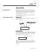
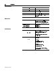
In diagnostic mode, the first line of the display indicates the mode and
serial port configuration:
Every byte received on either the RS-232 or RS-485 port is displayed
in a hexadecimal format on line 2 of the display. The bytes shift from
right to left as each new byte is received. The byte on the right is
always the last byte received. For example:
The value of every byte is displayed including control characters.
Characters are displayed as fast as they are received (no buffer). This
usually means that only the last 7 bytes of a long message are
viewable.
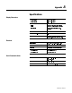
DIAG: 19200 N-8-1
19200
9600
1200
300
Baud Rate
Parity / Data Bits / Stop Bits
N - 8 - 1
E - 7 - 1
O - 7 - 1
DIAG: 19200 N-8-1
Slave 5, Line 1, Carriage Return
05 01 0D