
USER MANUAL User guide


Publication 2706-6.3
Options
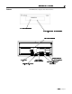
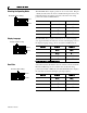
Positions #7 and #8 determine the parity, set the parity to match the
host device. Positions #9 and #10 apply to Terminal mode operation,
Refer to Chapter 6.
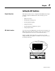
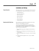
Serial Address
Position #1 through #7 of DIP Switch #2 select the serial address of
the slave display. The address is the binary sum of the value of all of
the switches in the Up condition. Position #7 is the least significant
position (ones position) and position #1 has the most significant value
(64 position) as shown below. Positions #8 to #10 are not used.
Refer to Appendix C for a list of all possible addresses and the
corresponding switch positions.
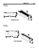
For example, with Positions #2, #4, and #5 in the up condition, the
serial address is 44.
Important: Address 13 and 18 are invalid slave addresses. If you
assign either of these addresses to a slave, the slave overrides the
setting and internally switches the address to 127.
12 345678910
Even Parity Enabled
DIP #1
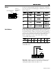
DIP #2
12 345678910
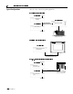
Cursor &
Auto New Line
Disabled
↑
↓
↑
↓
↑
↓
↑
↓
12 345 6 7 8910
32
8
4
44
Not Used