Allen-Bradley Dataliner DL40 Plus Slave Displays Cat. No.
Important User Information Because of the variety of uses for the products described in this publication, those responsible for the application and use of this control equipment must satisfy themselves that all necessary steps have been taken to assure that each application and use meets all performance and safety requirements, including any applicable laws, regulations, codes and standards.
x-2
Table of Contents Preface Overview of this Manual . . . . . . . . . . . . . . . . . . . . . . . . . . .P-1 Chapter Objectives . . . . . . . . . . . . . . . . . . . . . . . . . . . . . . .P-1 Intended Audience . . . . . . . . . . . . . . . . . . . . . . . . . . . . . . .P-2 Conventions Used . . . . . . . . . . . . . . . . . . . . . . . . . . . . . . . .P-2 Related Publications . . . . . . . . . . . . . . . . . . . . . . . . . . . . . .
tocii Table of Contents Installation and Startup Chapter 3 Chapter Objectives . . . . . . . . . . . . . . . . . . . . . . . . . . . . . . . . . .3-1 Mounting the DL40 Slave . . . . . . . . . . . . . . . . . . . . . . . . . . . . .3-1 Panel Cutout Dimensions . . . . . . . . . . . . . . . . . . . . . . . . . . . . .3-2 Dimensions, 2-Line Display. . . . . . . . . . . . . . . . . . . . . . . . . . . .3-3 Dimensions, 4-Line Display . . . . . . . . . . . . . . . . . . . . . . . . . . .
Table of Contents PanelView (PV) Slave Mode tociii Chapter 5 Chapter Objectives . . . . . . . . . . . . . . . . . . . . . . . . . . . . . . . . . .5-1 PV Slave Mode . . . . . . . . . . . . . . . . . . . . . . . . . . . . . . . . . . . . .5-1 PV Mode Protocol . . . . . . . . . . . . . . . . . . . . . . . . . . . . . . . . . . .5-1 Display Options . . . . . . . . . . . . . . . . . . . . . . . . . . . . . . . . . . . .5-2 [Ctrl][F](06 hex) . . . . . . . . . . . . . . . . . . . . . . . . . . . . . . . . . .
tociv Table of Contents Specifications Appendix A Display Characters . . . . . . . . . . . . . . . . . . . . . . . . . . . . . . . . A-1 Electrical . . . . . . . . . . . . . . . . . . . . . . . . . . . . . . . . . . . . . . . A-1 Serial Communications . . . . . . . . . . . . . . . . . . . . . . . . . . . . A-1 Environmental . . . . . . . . . . . . . . . . . . . . . . . . . . . . . . . . . . . A-2 Mechanical . . . . . . . . . . . . . . . . . . . . . . . . . . . . . . . . . . . . . A-2 Certifications. . .
Preface Using this Manual Chapter Objectives Overview of this Manual Read this chapter to familiarize yourself with the rest of the Dataliner DL40 Plus Slave Message Display manual. You will learn about: • contents of this manual • intended audience • conventions used • related publications This manual describes how to install and use your DL40 Plus Slave display.
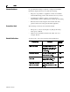
P-2 Preface Intended Audience Conventions Used Related Publications No specialized knowledge is required to configure and install the DL40 slave display. However, we assume the following: • The person responsible for equipment connections is familiar with standard wiring practices and electrical codes in your area. • Communication cabling is done by a person having an understanding of basic communications terminology and cabling.
Chapter 1 Introduction to the DL40 Plus Slave Chapter Objectives Description This chapter describes the DL40 Plus Slave display and summarizes its capabilities. The following topics are included in this chapter: • DL40 Plus Slave description • Operating modes • Features • Typical configurations The DL40 Plus Slave displays are available in two-line and four-line versions. These displays are designed for panel mounting in industrial environments and require a 110-240V AC power source.
1-2 Introduction to the DL40 Plus Slave Operating Modes The DL40 Plus Slave has four operating modes: • DL Slave • PV Slave • Terminal • Diagnostic DL (Dataliner) Slave Mode Use this mode when connecting the DL40 Plus Slave to a DL40 Plus master display or an enhanced PanelView terminal such as the PV1400e. One or more DL40 Plus Slaves may be connected to a single DL40 Plus using an RS-485 link (multidrop) or an RS-232 link (single drop only).
Introduction to the DL40 Plus Slave Features 1-3 DL40 Plus Slave displays have these features: DL40 Plus 5 x 7 Dot Matrix Characters Two or Four-Line Vacuum Fluorescent Display DIP Switch Configuration Operates on standard RS-485 Port 12V DC Supply for Relay Connections Half-duplex RS-232 Port 100 - 240V AC, 50/60 Hz Relay with N.O. Contacts (3 Amp rated) Publication 2706-6.
1-4 Introduction to the DL40 Plus Slave Typical Configurations Here are some of the most typical applications: DL40 Plus to DL40 Plus Slave Other Slaves DL40 Plus Slave SYSTEM CHECK NORMAL DL40 Plus Slave DL40 Plus (Master) RS-485(multidrop) RS-232 (point-to-point) PRESS #1 STOPPED CHECK PRESS #1 Other Slaves Host Controller or Personal Computer Triggering Messages PanelView to DL40 Plus Slave DL40 Plus Slave INLET VALVE CLOSED 12:48 09/16/98 Printer Port RS-232 One Slave Only (Not Individua
Chapter 2 Setting the DIP Switches Chapter Objectives DIP Switch Location This chapter describes how to configure the DL40 Plus Slave display using the configuration DIP switches. The following topics are provided: • DIP switch location • Selecting the operating mode • Selecting display language • Setting the baud rate • Selecting display/communication options • Setting display address Access the 10-position DIP switches from the back of the display.
2-2 Setting the DIP Switches Selecting the Operating Mode Mode (DL Slaves Setting) The DL40 Plus Slave display operates in one of four modes. Chapter 1 briefly describes these modes. For detailed descriptions refer to the individual chapters describing each mode. Select the mode using position #1 and #2 of DIP Switch #1.
Setting the DIP Switches Options Cursor & Auto New Line Disabled Even Parity Enabled Positions #7 and #8 determine the parity, set the parity to match the host device. Positions #9 and #10 apply to Terminal mode operation, Refer to Chapter 6.
2-4 Setting the DIP Switches Publication 2706-6.
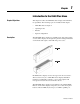
Chapter 3 Installation and Startup Chapter Objectives Mounting the DL40 Plus Slave This chapter describes how to mount and make electrical connections to the DL40 Plus Slave display. The following topics are described: • Mounting Instructions • Panel Cutout Dimensions • RS-232 Connections • RS-485 Connections • Relay Connections • Power Connections • Powerup Sequence The following pages provide panel cutout dimensions and overall dimensions for the DL40 Plus Slave displays.
3-2 Installation and Startup Panel Cutout Dimensions All dimensions are in inches (millimeters) Cutout 13.62 (345.9) 0.19 (4.8) Cutout 3.50 (88.9) 0.19 (4.8) 6.81 (173.0) 2-Line Slave Display 6.94 (176.1) 3.88 (98.4) 0.25 (6.4) Diameter Hole 6 places 13.87 (352.3) Cutout 13.62 (345.9) 0.19 (4.8) Cutout 5.30 (134.6) 0.19 (4.8) 6.81 (173.0) 4-Line Slave Display 6.94 (176.1) 0.25 (6.4) Diameter Hole 6 places 13.87 (352.3) Publication 2706-6.3 5.68 (144.
3-3 Installation and Startup Dimensions 2-Line Display 13.16 (334.2) 4.38 (111.3) 14.357 (365.0) 3.16 (80.3) 3.19 Dimensions are in inches (millimeters) (81.0) Dimensions 4-Line Display 6.16 (156.4) 13.16 (334.2) 14.357 (365.0) 3.16 (80.3) Dimensions are in inches (millimeters) 3.19 (81.0) Publication 2706-6.
3-4 Installation and Startup Electrical Precautions Install the DL40 Plus Slave display conforming to NFPA 70E, Electrical Safety Requirements for Employee Workplaces. In addition to the NFPA general guidelines, refer to the following: Careful cable routing helps minimize electrical noise. Route incoming power to the module by a separate path from the communication cables.
Installation and Startup RS-232 Connections 3-5 Use the RS-232 port to connect the DL40 Plus Slave to: • DL40 Plus Master • PanelView Printer Port • 1771 or 1746-DB BASIC Module • PLC-5 Channel 0 • SLC Channel 0 The following figure shows the location and terminal definitions for the RS-232 port.
3-6 Installation and Startup DL40 Plus Slave to PanelView RS-232 Printer Port Connect the DL40 Plus Slave to a PanelView RS-232 printer port as shown below. The PanelView sends messages to the DL40 using its print messages function. You can also use the DTAM Plus programming cable (Catalog No. 2707-NC2) with a male-female pin adapter.
3-7 Installation and Startup DL40 Plus Slave to PLC-5 Channel 0 Connect the DL40 Plus Slave to a PLC-5 Channel 0 port as shown below. You can also use programming cable (Catalog No. 2706NC12).
3-8 Installation and Startup RS-485 Connections Use the RS-485 port to connect the DL40 Plus Slave to: • DL40 Plus Master • Personal Computer using an RS-485 Converter The following figure shows the location and terminal definitions for the RS-485 port. DL40 Plus Slave Publication 2706-6.
3-9 Installation and Startup Connecting to a DL40 Master One or multiple DL40 Plus Slave displays may be connected to a single DL40 Plus master display using the RS-485 port. The RS-485 network supports multi-drop communications with up to 126 slave displays. Use Belden 9842 cable at a maximum length of 4,000 ft (1219 meters). Refer to the following illustration.
3-10 Installation and Startup DL40 Plus Slave to a Computer using an RS-485 Converter Box If you are using a personal computer to send messages to the DL40 Plus Slave using the RS485 port, refer to the following diagram: DL40-Plus Slave Display- RS-485 Port Term 6 CH-B 5 CH-A 4 Comm 3 Shield 2 RS-485 Converter Box (Model LD-485A-MP) RXB RXA E-Ground 1 TXB TXA Monitor Computer 2 3 5- Ground 3- TXD 7 2- RXD Shield Sheild RS-232 Ground P.C.
3-11 Installation and Startup Relay Connections Use the DL40 plus slave relay to trigger a remote alarm or warning light. The relay has contacts rated at 3A at 250V AC. Connect the remote alarm or light to the relay connectors on the back of the DL40 Plus Slave. Shown below is a typical wiring application. ! ATTENTION: Use the Alarm Relay for annunciator purposes only. Do not use it for control circuits.
3-12 Installation and Startup Power Connections Before making power connections, make sure that the power is turned off. The DL40 Plus Slave requires 100-240Volts AC, 50/60 Hz, 0.60 0.25 Amperes. ! ATTENTION: Improper wiring of the power connections may result in damage to the DL40. L1 Black (Brown) L2N White (Blue) Green (Green/Yellow) Important: Make sure all DIP switches are properly set as described in Chapter 2 before applying power. Publication 2706-6.
3-13 Installation and Startup Startup Sequence When power is applied to the DL40 Plus Slave a powerup sequence of displays are shown. The first display on powerup is the sign-on banner identifying the hardware and firmware: DL40 PLUS SLAVE 2L VER 1.00 (10/16/98) Following the sign-on banner, all of the display pixels are turned on for 2 seconds followed by a series of informational messages indicating the current DIP switch settings. Each display lasts for about four seconds.
3-14 Installation and Startup Publication 2706-6.
Chapter 4 Dataliner (DL) Slave Mode Chapter Objectives Slave Mode Operation This chapter describes the operation of the DL40 Plus Slave in DL Slave Mode. This chapter contains the following topics: • Slave mode description • Slave mode protocol • Example messages • Display options • Clearing one or more lines • Energizing relay Dataliner (DL) Slave mode allows multiple slave displays to display different messages while connected to a single master device.
4-2 Dataliner (DL) Slave Mode Slave Mode Protocol Messages sent to the DL40 Plus Slave in DL Slave mode must have the following format: 20 Characters to Display Slave Address Line Number Carriage Return If you are using a DL40 Plus as the master, configure its communication port for DL Slaves (refer to the DL40 Plus user manual, Publication 2706-6.1). This configures the DL40 master to send message data in the DL Slave format. 20 Characters to Display Send the message text characters to be displayed.
4-3 Dataliner (DL) Slave Mode Example Messages For example, a print statement for a Catalog No. 1771-DB Basic module with a DL40 Plus Slave display would be: Slave 1 Line 1 Carriage Return 100 PRINT #”VALVE NUMBER 1 OPEN”, CHR(1), CHR(1), CHR(13) The message VALVE NUMBER 1 OPEN would be displayed on line one of slave number one. Note that to send the message fields, the print CHR (decimal character equivalent) function is used.
4-4 Dataliner (DL) Slave Mode Clearing One or More Lines To clear one or more lines on a DL40 Plus Slave, use: Slave Address Line Number Carriage Return The following table lists the line number byte required for clearing any or all lines of the display.
Chapter 5 PanelView (PV) Slave Mode Chapter Objectives PV Slave Mode This chapter describes the operation of the DL40 Plus Slave in the PV Mode. The following topics are described: • PV Slave Mode description • PV Mode protocol • Display options Use the PanelView (PV) Slave Mode to send the DL40 Plus Slave messages from a PanelView operator terminal. The DL40 acts like a printer attached to the PanelView communication port.
5-2 PanelView (PV) Slave Mode Display Options Use the following control codes to control the appearance of messages displayed in PV Mode. [Ctrl][F] (06 hex) Flash code. Send the [Ctrl][F] command when you want the display characters to flash. All characters following the first flash code in a message flash. If two [Ctrl][F] codes appear in a message, only the characters between the codes flash. You can turn flash on and off multiple times in a message.
PanelView (PV) Slave Mode Line Display Characteristics 5-3 The PanelView Slave mode has two special display characteristics that make messages easier to read: Line to Line Delay After each individual line is displayed, there is a one second pause before the next line is displayed. This delay provides time for each line to be read. Cursor Movement Command Delay Line wrap, carriage return, line feed and form feed operations are not executed immediately.
5-4 PanelView (PV) Slave Mode Publication 2706-6.
Chapter 6 Terminal Mode Chapter Objectives Terminal Mode Operation This chapter describes the operation of the DL40 Plus Slave in Terminal Mode. This chapter contains the following topics: • Terminal mode operation • Protocol Terminal mode allows more control over messages than the basic Slave Mode setting.
6-2 Terminal Mode Terminal Mode Protocol Message text and control codes are sent serially to the DL40 Plus Slave in terminal mode. The following control codes are used: Cursor Up (Ctrl-K ) (0B hex) Positions the cursor directly above the current cursor position. If the cursor is on the first line, the cursor is moved to the last line on the display. Cursor Down (Ctrl-V) (16 hex) Positions the cursor directly below the current cursor position.
6-3 Terminal Mode New Line (Ctrl-_) (1F hex) Moves the cursor to the beginning of the line below. If the cursor is on the last line, every line is moved up one line and the bottom line is cleared. Delete Line (Esc and then R) (1B, 52 hex) Clears the current line. The cursor remains at its current position. Insert Line (Esc and then E) (1B, 45 hex) Moves the current line and all lines below it down one line (text on bottom line is removed). Then clears the current line.
6-4 Terminal Mode Set Flashing Mode (ESC G 2) (1B, 47, 32 hex) Enables flashing text mode. All characters received after this command are displayed flashing until disabled with a Clear Flashing Mode command. Clear Flashing Mode (ESC G 0) (1B, 47, 30 hex) Disables flashing text mode. Monitor Mode (ESC U) (1B, 55 hex) Displays all control codes as custom characters. These characters represent the hexadecimal value of the control code. Any command associated with the control code is ignored.
Chapter 7 Diagnostic Mode Chapter Objectives This chapter describes the operation of the DL40 Plus Slave in the Diagnostic Mode. Use the diagnostic mode to verify communications with a host device. Diagnostic mode displays the exact data being sent by a host device. Use the diagnostic mode as a temporary installation and troubleshooting aid. Set the DL40 Plus Slave for diagnostic mode using the DIP switch settings described in Chapter 2.
7-2 Diagnostic Mode Data Errors If the DL40 Plus Slave and host are not set to the same serial port settings, a reception error occurs. The error symbol is a ! displayed as the last character on line 1. This symbol is displayed for 1/5 sec (200 msec) after each serial error. Serial Port Error DIAG: 19200 N-8-1 ! 05 01 0D Note: Data cannot be displayed when a serial port error occurs. Publication 2706-6.
Appendix A Specifications Display Characters Character Height Two line display Four line display Character Set English Cyrillic International 11.3 mm (0.44 inch) 11.3 mm (0.44 inch) Standard & Extended ASCII Characters Standard & Cyrillic (Russian) Characters Standard & International ISO 8859-1 Characters Characters per Display Line 20 Viewing Distance - Approximate 7.6 meters (25 feet) Character Type Vacuum fluorescent, 5 x 7 dot matrix characters. Filtered to blue/green color.
A-2 Specifications Environmental Temperature Range - Operating Temperature Range - Storage Humidity Shock Vibration 0° to 60°C (+32° to 140°F) -40° to 85°C (-40° to 185°F) 5% to 95% (non-condensing) Operating 15G, Non-operating 30G pulses Operating 1.0G, Non-operating 2.5G sinusoidal Mechanical Enclosure Type Weight - Approximate Catalog No. 2706-LV2S Catalog No.
Appendix B Character Sets ASCII (English) Character Set Publication 2706-6.
B-2 Character Sets Extended ASCII Character Set Publication 2706-6.3 The following extended ASCII characters are available with all character sets (English, International, and Cyrillic).
Character Sets Cyrillic Character Set B-3 The Cyrillic character set is enabled when position #3 is On and position # 4 is Off on DIP Switch 1. Publication 2706-6.
B-4 Character Sets International Character Set Publication 2706-6.3 The International character set is enabled when position #3 is Off and position # 4 is On (DIP Switch 1).
Appendix C Slave Address Settings Address 1 2 3 4 5 6 7 00 OFF OFF OFF OFF OFF OFF OFF 01 OFF OFF OFF OFF OFF OFF ON 02 OFF OFF OFF OFF OFF ON 03 OFF OFF OFF OFF OFF ON 04 OFF OFF OFF OFF ON 05 OFF OFF OFF OFF ON 06 OFF OFF OFF OFF 07 OFF OFF OFF OFF 08 OFF OFF OFF 09 OFF OFF OFF 10 OFF OFF 11 OFF OFF 12 OFF 13 OFF 14 15 Address 1 2 3 4 5 6 7 38 OFF ON OFF OFF ON ON OFF 39 OFF ON OFF OFF ON ON ON OFF 40
Slave Address Settings C-2 Address Address 1 2 3 4 5 6 7 1 2 3 4 5 6 7 76 ON OFF OFF ON ON OFF OFF 121 ON ON ON ON OFF OFF ON 77 ON OFF OFF ON ON OFF ON 122 ON ON ON ON OFF ON OFF 78 ON OFF OFF ON ON ON OFF 123 ON ON ON ON OFF ON ON 79 ON OFF OFF ON ON ON ON 124 ON ON ON ON ON OFF OFF 80 ON OFF ON OFF OFF OFF OFF 125 ON ON ON ON ON OFF ON 81 ON OFF ON OFF OFF OFF ON 126 ON ON ON ON ON ON OFF 82
Appendix D SLC/PLC Program Examples PLC-5 Channel 0 to DL40 Plus Slave This program assumes that the message text is entered in the string file ST30:10. This file contains the message text and defines the slave number and line number the mesage is to be displayed on. Refer to page 4-3 for an example message. PLC-5 Channel 0 to Dataliner DL40 Slave in DL Slave Mode, PLC-5 in User-Mode TON EN Timer On Delay 0000 String sent to DL40 Slave at serial address 01, line 01. 0001 Timer T4:1 Time Base 0.
D-2 SLC/PLC Program Examples SLC Channel 0 to DL40 Plus Slave Channel 0 of SLC connected to DL40 Slave operating in DL Slave mode. This timer is used to continuously send ASCII data to the TON DL40 slave display. EN Timer On Delay 0000 Timer Time Base T4:0 1.0 Preset 4< Accum 0< DN This concatenate instruction allows the message text to be entered separately from the control instructions.
Index A address Dataliner slave mode 4-2 invalid adresses 2-3 settings C-1 alarm relay connections 3-11 control of 4-4, 5-2, 6-3 specifications A-1 DL40 slave to 1771 BASIC module 3-6 DL40 slave to PanelView printer port 3-6 DL40 slave to PLC-5 3-7 DL40 slave to SLC 3-7 electrical precautions 3-4 input power 3-4 PanelView to DL40 slave 1-4 PLC, PC, other device to DL40 slave 1-4 relay 3-11 RS-232 3-5 RS-485 3-8 applications DL40 master to Dl40 slave 1-4 PanelView to DL40 slave 1-4 PLC, PC, other device to
I2 Index DIP switches address settings 2-3, C-1 baud rate 2-2 selecting language 2-2 selecting operating mode 2-2 selecting options 2-3 display options Dataliner slave mode 4-3 DL Slave Mode 1-2 E electrical DL40 slave to 1746 BASIC module 3-6 DL40 slave to 1771 BASIC module 3-6 DL40 slave to DL40 master 3-5, 3-9 DL40 slave to PanelView printer port 3-6 DL40 slave to personal computer 3-10 DL40 slave to PLC-5 3-7 power connections 3-4, 3-12 relay conections 3-11 electrical precautions 3-4 enclosure ratin
Index O operating modes 1-2 selecting 2-2 options selecting 2-3 P panel cutout dimensions 3-2 PanelView slave mode carriage return 5-2 cursor movement delay 5-3 display options 5-2 energize relay 5-2 flash code 5-2 form feed 5-2 line feed 5-2 line to line delay 5-3 relay reset 5-2 parity setting 2-3 PLC D-1 program example D-1 power connections 3-12 requirements A-1 protocol slave mode 4-2, 5-1 terminal mode 6-2 publications related P-2 PV slave mode 1-2 R relay connections 3-11 control of 4-4, 5-2 speci
I4 Index delete line 6-3 display status 6-4 energize relay 6-3 flashing mode 6-4 insert line 6-3 line feed 6-2 monitor 6-4 new line 6-3 reverse line feed 6-2 set cursor invisible 6-3 set cursor position 6-3 set cursor visible 6-3 U UL listing A-2 V vibration A-2 viewing distance A-1 voltage input requirements 3-4, A-1 Publication 2706-6.
Publication 2706-6.3 - December 1998 41061-096-01(A) © (1998) Rockwell International Corporation. Printed in the U.S.A.