
USER MANUAL Manual

Parallel Port Communications 7–9
Publication 2706-6.1
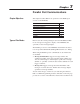
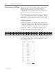
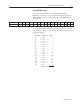
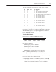
The strobe line states specify the type of data on the data lines.
MS3 MS2 MS1 MS0 Data Type
0 0 0 0 null
0 0 0 1 D0–D15 contain the message number
0 0 1 0 D0–D15
contain the slave address
0 0 1 1 D0–D9 BCD sign bits for
(Ctrl V) variables 1–10
1 0 0 0 D0–D15 contain variable 1
1 0 0 1 D0–D15 contain variable 2
1 0 1 0 D0–D15 contain variable 3
1 0 1 1 D0–D15 contain variable 4
1 1 0 0 D0–D15 contain variable 5
1 1 0 1 D0–D15 contain variable 6
1 1 1 0 D0–D15 contain variable 7
1 1 1 1 D0–D15 contain variable 8
0 1 1 0 D0–D15 contain variable 9
0 1 1 1 D0–D15 contain variable 10
The number you assign to a variable by setting strobe lines does not
necessarily correspond to the position of the variable in a message.
The DL40 Plus expects to see all
[CTRL][V] variables numbered
before
[CTRL][W] variables.
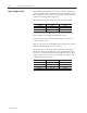
Triggering Rules Example
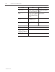
If a message has variables positioned as follows:
[CTRL][V] [CTRL][W] [CTRL][V] [CTRL][W] [CTRL][V]
First
Position
Second
Position
Third
Position
Fourth
Position
Fifth
Position
they must be numbered:
[CTRL][V] first position = Variable 1
[CTRL][V] third position = Variable 2
[CTRL][V] fifth position = Variable 3
[CTRL][W] Second and fourth position = Variable 4
Note:
[CTRL][V] variables always use a (16 bit) word;
[CTRL][W] variables do not use a full (16 bit) word.
If the variables are not numbered as shown, they would be displayed
in wrong positions and possibly corrupted.
• If [CTRL][W] variables are ASCII (8 bit) variables, [CTRL][W]
second position
would be sent in the high byte of Variable 4;
fourth position would be sent in the low byte of Variable 4.