
USER MANUAL Manual

Parallel Port Communications 7–6
Publication 2706-6.1
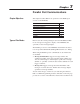
Each parallel input interprets two voltage levels: ON or OFF. There
is also a third state which should be avoided, an indeterminate state.
The indeterminate state occurs when the voltage is between the ON
voltage range and the OFF voltage range.
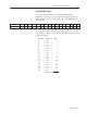
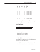
The table below lists the voltage levels and their logic values.
Voltage Range High True Logic Low True Logic
0 – 0.8 VDC 0 (OFF) 1 (ON)
0.8 – 3.5 VDC Indeterminate Indeterminate
3.5 – 24 VDC 1 (ON) 0 (OFF)
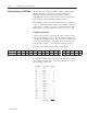
You can select either the High True or Low True Logic using the
Onboard Editor or the Offline Programming software.
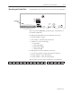
To ensure proper data, the GND terminal must be connected as a
voltage reference point.
Note: You can use 120 volt AC/60 Hz input voltages if two Catalog
Number 2706-NG2 Input Converters are used.
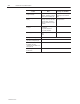
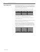
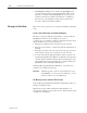
The parallel port is compatible with Allen-Bradley’s DC Output
Modules as outlined in the table below. Two 2706-NG2 AC input
converters are required with the AC Output Module. The 12 VDC
output connection can be used to power the DC connections of the
2706–NG2 AC input converters.
AC Output Modules DC Output Modules
1
PLC 1771-OAx 1771-OBx
SLC 1746-OAx 1746-OBx
Flex I/O 1794-OAx 1794-OBx
ControlLogix 1756-OAx 1756-OBx
1
We recommend that you use DC sourcing output modules.
Logic Voltage Levels