
USER MANUAL Manual

Parallel Port Communications 7–4
Publication 2706-6.1
The Parallel port uses either the Binary or Binary Coded Decimal
(BCD) numbering system to transfer message numbers and
[CTRL][V] (formatted) variables. It uses BCD or ASCII for
[CTRL][W] (unformatted) variables. Select a data format using the
Onboard Editor or the Offline Programming Software.
The numbering system you use is usually based on the format used
by your controller. With binary numbers you can input variable data
in the range of –32,768 to +32,767 (2’s complement binary). With
BCD numbers, the variable data can range from –9,999 to +9,999.
Using Binary Data Input
A data line may either be at ground level or have a voltage present.
A voltage representing a value of 1 and ground representing a value
of 0, is known as High True Logic. The opposite is Low True Logic.
You can set the DL40 Plus to accept High True or Low True Logic
using the Onboard Editor or the Offline Programming Software.
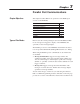
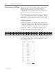
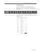
The table below shows the binary value of each data line.
Data Line D15 D14 D13 D12 D11 D10 D9 D8 D7 D6 D5 D4 D3 D2 D1 D0
Data Line Value 32768 16384 8192 4096 2048 1024 512 256 128 64 32 16 8 4 2 1
MSB LSB
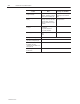
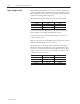
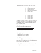
For example, assume the following logic levels appear for each data
line. Adding the binary values of the individual data lines provides
the value being entered, 145.
Data Line Logic Level Value
D0
D1
D2
D3
D4
D5
D6
D7
D8
D9
D10
D11
D12
D13
D14
D15
=
=
=
=
=
=
=
=
=
=
=
=
=
=
=
=
Logic 1
Logic 0
Logic 0
Logic 0
Logic 1
Logic 0
Logic 0
Logic 1
Logic 0
Logic 0
Logic 0
Logic 0
Logic 0
Logic 0
Logic 0
Logic 0
=
=
=
=
=
=
=
=
=
=
=
=
=
=
=
=
1
0
0
0
16
0
0
128
0
0
0
0
0
0
0
0
Sum of all values
145
Selecting Binary or BCD Data