
USER MANUAL Manual

Remote I/O Application Examples E–13
Publication 2706-807
Triggering Messages Using Block Transfers -
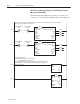
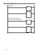
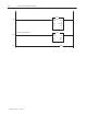
PLC5 Program Example (Bit Trigger Run Mode)
Note: If Block Transfer DIP Switch (Switch 2-4) is enabled, all
exchanges between the PLC & DL40 Plus must be Block Transfers.
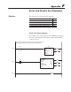
PLC–5 at rack #1, group #0
(No priority section in this example. If a priority section is needed, set the
priority size in the Triggering Port Settings menu in the onboard editor.)
Block Transfer Read
Module Type Generic Block Transfer
Rack 001
Group 0
Module 0
Control Block N11:0
Data File N9:0
Length 13
Continuous No
BTR
0000
0001
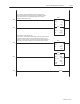
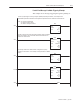
Move
Source 0
0<
Dest N9:2
0<
MOV
0002
0003
BTR_ENABLE
N11:0
BTW_ENABLE
N11:5
15 15
<EN>
<DN>
<ER>
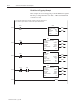
Block Transfer Write
Module Type Generic Block Transfer
Rack 001
Group 0
Module 0
Control Block N11:5
Data File N9:40
Length 32
Continuous No
BTW
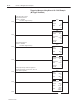
BTW_ENABLE
N11:5
BTR_ENABLE
N11:0
15 15
<EN>
<DN>
<ER>
Trigger message #1 here:
Format: 0 = Disabled
1 = Enabled. Trigger message
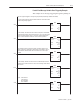
(In Bit Trigger Mode, each bit of each word of the Block Transfer Write corresponds
to a message number to be triggered. Messages 1–465 can be triggered in this way.
The Bit Field Distributor “turns on” the messages by setting the bit
corresponding to a message number in the Block Transfer Write table.
Bit Field Distributor
Source N9:2
0<
Source Bit 0
Dest N9:41
0<
Dest Bit 0
Length 1
BTD