
USER MANUAL Manual

Remote I/O Application ExamplesE–10
Publication 2706-807
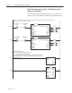
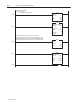
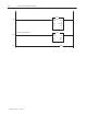
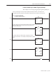
Block Transfer Message Triggering - PLC5 Example Program
(Message List Run Mode)
Note: If Block Transfer DIP Switch (Switch 2–4) is enabled, all
exchanges between the PLC & DL40 Plus must be Block Transfers.
S
witc
h 2
–
4
on
DL40
Plu
s
mu
s
t
be
enabled
. Sp
ecial
me
ss
a
g
e
s sh
ould
be
tri
gg
ered
onl
y
a
s p
riorit
y
me
ss
a
g
e
s.
They should not be added to the message list.
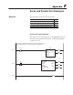
Block Transfer Read
Module Type Generic Block Transfer
Rack 001
Group 0
Module 0
Control Block N11:0
Data File N9:0
Length 13
Continuous No
BTR
0000
0001
BTR_ENABLE
N11:0
BTW_ENABLE
N11:5
15 15
Block Transfer Write
Module Type Generic Block Transfer
Rack 001
Group 0
Module 0
Control Block N11:5
Data File N9:20
Length 13
Continuous No
BTW
BTW_ENABLE
N11:5
BTR_ENABLE
N11:0
15 15
<DN>
<EN>
<ER>
<EN>
<DN>
<ER>
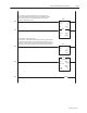
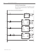
Move
Source 1
1<
Dest N9:3
0<
0002
Bit Field Distributor
Source N9:3
0<
Source Bit 0
Dest N9:20
9097<
Dest Bit 13
Length 1
BTD
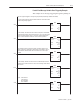
0003
Enter Add/Delete Bit here:
Format:0 = Delete Message from Message List
1 = Add Message to Message List
In Message List Mode, Word 1, Bit 15 of the Block Transfer Write corresponds
to the Add/Delete Bit. This tells the DL40 to add the message or delete the
message from the list.