
USER MANUAL Manual

Remote I/O Application ExamplesE–6
Publication 2706-807
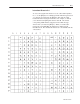
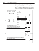
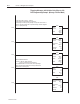
Clock and Date Data Return – PLC5 Programming Example
(Any Run Mode)
< >
<DN>
This program is used with Special Messages 912 and 913. Message 912 returns clock data. Message 913 returns
date data. This program captures the clock and date data returned from the DL40 Plus to the PLC. Any of the run
modes are compatible with this program.
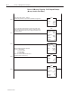
Block Transfer Read
Module Type Generic Block Transfer
Rack 001
Group 0
Module 0
Control Block N11:0
Data File N9:0
Length 13
Continuous No
BTR
0000
0001
0002
Move
Source N9:0
912<
Dest N7:1
0<
MOV
0003
0004
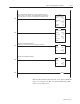
This rung is used for handshaking. It is recommended that when data is being
sent from the DL40 Plus to the PLC that handshaking be used. Switch Bank 2,
switch 7, must be set for this to work properly.
BTR_ENABLE
N11:0
BTW_ENABLE
N11:5
15 15
<EN>
<ER>
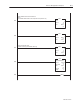
Block Transfer Write
Module Type Generic Block Transfer
Rack 001
Group 0
Module 0
Control Block N11:5
Data File N9:20
Length 13
Continuous No
BTW
BTW_ENABLE
N11:5
BTR_ENABLE
N11:0
15 15
<EN>
<DN>
<ER>
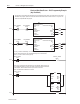
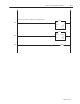
Word 0, bit 12, of the Block Transfer Read is the clock date bit. When this bit is set,
the clock/date information is in word 0 and word 1 of the Block Transfer Read table.
In this example, data from the DL40 Plus is placed in N7:1 and N7:2.
NOTE: The data from the DL40 Plus is in BCD
Move
Source N9:1
–28136<
Dest N7:2
14<
MOV
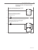
INPUT_SHAKE
N9:0
15
OUTPUT_SHAKE
N9:20
15
DATE_CLOCK
N9:0
12
<END>