
USER MANUAL Manual

DIP Switch Settings
This chapter describes the DIP switch settings for the Remote I/O
and Parallel I/O versions of the DL40 Plus.
Section Page
DIP Switches on Remote I/O Versions 10–1
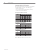
Setting Switch Bank #1 for PLC-2 Controllers 10–2
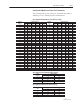
Setting Switch Bank #1 PLC-3, PLC-5 Controllers 10–3
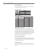
Setting Switch Bank #2 10–4
Setting Switch Bank #3 10–6
DIP Switches on Parallel Port Versions 10–10
Setting Switch Bank #1 10–11
Setting Switch Bank #2 10–12
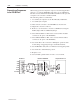
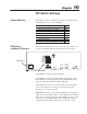
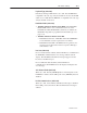
Three DIP switch banks are located on the back of the module. You
can access the DIP switches through a cutout, as shown below.
KEYBOARD
SW1
SW2
SW3
GND
RELAY
L1 L2N
RIO
2 S 1
RS-485
250 VAC 3A
12VDC
RS-232
Remote I/O Port
Location of DIP Switches
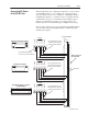
Switch Bank #1 (SW–1) sets the rack address.
Switch Bank #2 (SW–2) controls Baud Rate, Fast Reset Sequence,
Block Transfer, Last Chassis, Keyboard Type, Handshaking, Last
State, Select Enable, No PLC Comm Error Message.
Switch Bank #3 (SW–3) sets the serial address. The serial address
refers to the address used for triggers received from the serial
RS-485 port or computer keyboard.
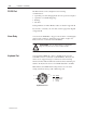
Important: Remove power from the DL40 Plus before setting any
switch except Select Enable, SW2–9. Select Enable can be switched
with power on. Switch settings are scanned only on power–up. The
new setting for Select Enable takes effect immediately. The new
settings for all other switches take effect on power–up or reset.
Chapter Objectives
DIP Switches
on Remote I/O Versions