Allen-Bradley Dataliner DL40 Plus Message Display Catalog No.
Important User Information Solid state equipment has operational characteristics differing from those of electromechanical equipment. “Safety Guidelines for the Application, Installation and Maintenance of Solid State Controls” (Publication SGI-1.1) describes some important differences between solid state equipment and hard–wired electromechanical devices.
Preface Preface Objectives . . . . . . . . . . . . . . . . . . . . . . . . . . . . . . . . . . . Overview of this Manual . . . . . . . . . . . . . . . . . . . . . . . . . . . . . . . . Intended Audience . . . . . . . . . . . . . . . . . . . . . . . . . . . . . . . . . . . . Conventions Used . . . . . . . . . . . . . . . . . . . . . . . . . . . . . . . . . . . . Related Publications . . . . . . . . . . . . . . . . . . . . . . . . . . . . . . . . . .
toc–ii Table of Contents Using Special Messages Chapter 3 Chapter Objectives . . . . . . . . . . . . . . . . . . . . . . . . . . . . . . . . . . . What are Special Messages? . . . . . . . . . . . . . . . . . . . . . . . . . . . . Description of Special Messages . . . . . . . . . . . . . . . . . . . . . . . . . Offline Operating Modes Chapter 4 Chapter Objectives . . . . . . . . . . . . . . . . . . . . . . . . . . . . . . . . . . . Help Mode . . . . . . . . . . . . . . . . . . . . . . . . . . . . . . .
Table of Contents Remote I/O Communications Chapter 8 Installation and Wiring Chapter 9 Chapter Objectives . . . . . . . . . . . . . . . . . . . . . . . . . . . . . . . . . . . Overview of Remote I/O Communications . . . . . . . . . . . . . . . . . . . Remote I/O Terminology . . . . . . . . . . . . . . . . . . . . . . . . . . . . . . . . Typical Configurations . . . . . . . . . . . . . . . . . . . . . . . . . . . . . . . . . Processors and Corresponding Scanners . . . . . . . . . . . . . . . . . . .
toc–iv Table of Contents DIP Switch Settings Chapter 10 Chapter Objectives . . . . . . . . . . . . . . . . . . . . . . . . . . . . . . . . . . . 10–1 DIP Switches on Remote I/O Version . . . . . . . . . . . . . . . . . . . . . . 10–1 DIP Switches on Parallel Port Version . . . . . . . . . . . . . . . . . . . . . .
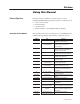
Preface Objectives Read this chapter to familiarize yourself with the rest of the Dataliner DL40 Plus Message Display manual. You will learn about: • contents of this manual • intended audience • conventions used • enhanced features of the DL40 Plus Message Displays Overview of this Manual This manual describes how to install and use your DL40 Plus Series Dataliner Message Display.
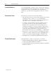
P–2 Using this Manual Intended Audience No special knowledge is needed to enter or edit messages. However, since the Dataliner message display must be connected to peripheral equipment, we assume you are familiar with communication terminology, especially when using the Remote I/O version with a PLC. Conventions Used The following conventions are used in this manual: • All menus and screens reproduced in this manual are approximate renderings of what you will see on your terminal screen.
Using this Manual Enhanced Features of the DL40 Plus Message Displays P–3 The Dataliner DL40 Plus Message Displays are the next generation of Allen–Bradley message displays, replacing the older Dataliner DL40, DL20, and DL10 Series Message Displays.
P–4 Using this Manual Regulatory Enhancements The DL40 Plus meets and is listed for the following environmental, safety, and European Union regulatory requirements: • European Union Directive Compliance – CE marked for: EMC Directive and LVD Directives. IEC 1131-2 Equipment Class I.
Overview of the DL40 Plus Chapter Objectives This chapter covers the following topics.
1–2 Overview of the DL40 Plus RS-485/RS-232 Communications Both the Remote I/O and Parallel Port versions have RS-485 and RS-232 ports. You can configure these ports for Programmer, DL Slave or Open Protocol communications (see table below). Port settings are modified through the Ports menu in the Offline Programming software or the Onboard Editor. You select a communication option under the Port Use submenu.
Overview of the DL40 Plus Message Support 1–3 The DL40 Plus stores messages of varying length. Each message is identified by a unique message number from 1 to 9999. Messages are placed in an internal memory queue when triggered by a command from your control system. They are then run according to attributes selected in the DL40 Plus.
1–4 Overview of the DL40 Plus Programming Features The DL40 Plus is a versatile status, prompt and diagnostic display tool, equipped with a full range of high-end programming and performance features.
Overview of the DL40 Plus 1–5 Offline Programming Software Create and edit application files using the Offline Programming Software (Catalog No. 2706-LSW) on a personal computer. With interactive menus you can quickly create messages, set message attributes, and download messages to one or more DL40 Plus displays. Create Message editing screen Download Message Files screen Set Message Attributes window Convert DL20 files for use with a DL40 Plus The offline programming cable (Catalog No.
1–6 Overview of the DL40 Plus PLC-5 Remote I/O PassThrough Via DH+ PLC-5 Remote I/O PassThrough lets you upload and download message files between a computer and a DL40 Plus connected by Remote I/O to a PLC on the DH+ link. Separate wiring from the computer to the DL40 Plus is not required. For a list of supported controllers, see page 1–14.
Overview of the DL40 Plus 1–7 International and Cyrillic Character Sets The local language character sets let you create and display messages in other languages such as French, German, Italian, and Spanish with the Offline Programming Software with: • English (default) • International character set ISO 8859–1 • Cyrillic (Russian) English characters are also available with both the International and Cyrillic character sets.
1–8 Overview of the DL40 Plus Historical Events Stack The Historical Events Stack records the occurrence and sequence of some or all messages and logs variable data values that have been triggered and/or displayed. The 16K bytes of stack memory holds about 1,000 events. You can view information in chronological order or by frequency of occurrence, or print the record. Clock Operations A real-time battery-backed clock keeps accurate time even when power is removed from the unit.
Overview of the DL40 Plus 1–9 Keyboard Port Use the Keyboard port on the DL40 Plus to: • edit options, messages, communication port settings • input ASCII data to a host controller, PLC, or computer • trigger messages using Open protocol (ASCII triggering) Debug Mode (Parallel Port Version) Use Debug mode to display the binary status (1 or 0 value) of the data lines and the state of the strobe lines. This mode is useful for checking the output of a programmable controller.
1–10 Overview of the DL40 Plus Background Messages Specify a background message that will display whenever the DL40 Plus has no other triggered messages in the queue. Hidden Messages Hidden messages do not appear on the DL40 Plus display or have any affect on what is being displayed. Hidden messages can be sent to a slave display, printed, or stored on the Historical Events Stack. Embedded Variables Messages can contain variable data. Variable values are received when the message is triggered.
Overview of the DL40 Plus 1–11 Adjustable Parameters for Serial Communications With the DL40 Plus, you can configure RS-232 or RS-485 port parameters as needed for compatibility with PLCs/SLCs, printers, slave displays, or control computers.
1–12 Overview of the DL40 Plus The Parallel port version of the DL40 Plus has 2 Run modes. • Message/Variable/Slave Mode triggers a message with 1 to 40 variables, depending on trigger method, and variable type. • Message List Mode triggers a message list of up to 20 messages in round robin order. To select Run mode, use the Onboard Editor or the Offline Programming Software. For more details on the various run modes, see Chapter 5, Online Operating Modes.
Overview of the DL40 Plus Special Messages 1–13 Special messages let you monitor and control certain functions of the DL40 Plus without leaving Run Mode. Special messages normally occupy message numbers 901 through 916. You can move special messages to message numbers 1 to 16, or disable them with the Offline Programming Software or Onboard Editor. For a complete description of special messages see Chapter 3, Using Special Messages.
1–14 Overview of the DL40 Plus Controller Support for Remote I/O The following PLCs and SLCs support Remote I/O communications with the DL40 Plus. • PLC-5/11, 5/15➀, 5/20, 5/25, 5/30, 5/40, 5/60, 5/80, 5/250 • PLC-2, PLC-5/10, 5/12 with Catalog Number 1771-SN Scanner • SLC-5/02, 5/03, 5/04 with Catalog Number 1747-SN Scanner➁ ➀ If you are using a PLC-5/15 with partial rack addressing and block transfers, you must use Series B, Rev. J or later. ➁ Block Transfer requires a Series B or later Scanner.
Overview of the DL40 Plus 1–15 PassThrough Support over an Ethernet Link The following table lists the Allen-Bradley PLCs that support PassThrough file transfers with the DL40 Plus message display over an Ethernet link as of this printing. PLC Types Series Revision PLC 5/40E A B E or later PLC 5/60E A B B or later PLC 5/80E All All PLC 5/250 All All Use one of the Allen-Bradley Ethernet computer interface boards (or its equivalent) for PassThrough file transfers.
1–16 Overview of the DL40 Plus Compatible Keyboards The following keyboards are compatible with the DL40 Plus. Catalog No. Description 6189-KBD1 Industrial Keyboard 6189-KBE1 Industrial Spill-Proof Keyboard 6186-KBM1 Industrial Panel Mount Membrane Keyboard Note: When used with the DL40 Plus, the Num Lock and Caps Lock indicators will not illuminate. Options and Accessories Options and accessories for the DL40 Plus are listed below.
Using the Onboard Editor to Create Messages Chapter Objectives This chapter shows how to use the Onboard Editor to manage messages (and message attributes) for the DL40 Plus.
2–2 Using the Onboard Editor to Create Messages Entering the Onboard Editor You must enter the Onboard Editor from Run mode or Help mode. Press [CTRL] [E] to enter the Onboard Editor. Use the menu tree on the next page as a guide to onboard editing. • Press [Y][↵ ] to access a function. • Press [N][↵ ] to go to the next function. • Press [Space Bar] to select or toggle through options with multiple choices.
Using the Onboard Editor to Create Messages Onboard Editor Menu 2–3 The following diagram provides an overview of the Onboard Editor’s menu structure.
2–4 Using the Onboard Editor to Create Messages Creating or Editing Messages Enter the MESSAGES function [Y][↵ ]. Enter the EDIT MESSAGES function [Y][↵ ]. Respond to the EDIT MSG prompt with a new message number to create a message or an existing message number to edit a message. Note: FILE FREE gives you the number of kilobytes remaining in user Memory.
Using the Onboard Editor to Create Messages Keyboard Functions 2–5 Messages can consist of: • ASCII text (including extended ASCII, international, or Cyrillic characters if you are using the Offline Programming Software) • variable data Create and edit messages using the keys below. Any alphabetic or numeric key ↑ ↓ ← → Inserts that character at the position of the cursor.
2–6 Using the Onboard Editor to Create Messages Inserting Variables in Messages You can send variables to the DL40 Plus from a PLC via the Remote I/O, RS-485, RS-232, or Parallel port. Variables can be sent to messages only in the Message/Variable/Slave or Message/Variable Run modes. To insert variables in a message, press the [CTRL] key in combination with a letter.
Using the Onboard Editor to Create Messages 2–7 Change Formatted Variable [CTRL][F] Use [CTRL][F] to change the formatting parameters of a variable. To do so, place the cursor under the symbol for the variable you want to change, then press [CTRL][F].
2–8 Using the Onboard Editor to Create Messages Insert Request for ASCII Input Data [CTRL][X] A data request requires you to enter ASCII Data (8-bit ASCII character) through the Keyboard port into the displayed message. • When returning ASCII Input Data via RS-485/RS-232 Port, the message requesting the data must be triggered via the RS-485 port. This is true for both Parallel Port and Remote I/O units. Data is automatically entered when you press [↵ ].
Using the Onboard Editor to Create Messages 2–9 Insert Date Into a Message [CTRL][Y] To enter the date in a message, place the cursor after the point where you want the date to appear, then press [CTRL][Y]. The software will insert the date symbol DAY MON DT (the numerical day of the month). You can use the date variable only once in a given message. The date variable occupies 10 of the available 20 characters on a display line.
2–10 Using the Onboard Editor to Create Messages Display Line This value controls where on the DL40 Plus display the message will appear. Options are different for 2 and 4 line versions. Use the spacebar to move through the available choices, then press [↵ ] when you see the correct value.
Using the Onboard Editor to Create Messages 2–11 Send to Slave If you enter a slave address number, the message is sent to the slave each time it is triggered. However, in Message/Variable/Slave mode, a slave address sent with the message trigger overrides this attribute. Important: To send any message to a slave, Port Use for the RS-232 or RS-485 port must be set to DL Slave. If the AutoRepeat attribute is active, the message is sent to the slave each time it repeats.
2–12 Using the Onboard Editor to Create Messages AutoClear Activating this attribute tells the DL40 Plus to clear the message from the display after the Wait Time for the message has expired, even if no other messages are triggered. This value applies only to the lines used by a single message. For example, if this message uses line 2 only, then line 2 is cleared. Lines 1, 3 and 4 remain unchanged. Important: AutoClear de-energizes the alarm relay only if the message cleared had energized the relay.
Using the Onboard Editor to Create Messages 2–13 Energize Relay Activating this attribute displays the message and energizes the display’s alarm relay whenever the message is triggered. The alarm relay will not de-energize even after the Wait Time has expired.
2–14 Using the Onboard Editor to Create Messages Hide Message This attribute suppresses the message from displaying on the DL40 Plus but does send it to a slave display, printer, or place it on the Historical Events Stack. The other attribute settings for the message determine its destination(s). For example, assume the Hide message, Print message and Send to Slave 2 attributes are enabled.
Using the Onboard Editor to Create Messages 2–15 Slave Message Echo Relay This attribute sends the energize relay command to the DL40 Plus or DL50 slave addressed in the Send message to slave number attribute. These commands are sent in addition to any specified message text.
2–16 Using the Onboard Editor to Create Messages To modify options: 1. Press [CTRL][E] to enter the Onboard Editor. 2. Press [↵ ] in response to the query Messages? 3. Press [Y] to the query Options? The Onboard Editor displays each modifiable option and gives you a chance to accept the current value or enter a new one. Use the spacebar to move through the available settings, and press [↵ ] to accept your choice. Each time you press [↵ ], you move to the next option.
Using the Onboard Editor to Create Messages 2–17 Newest Message on Line 1 This option displays the newest message to be triggered on line 1 and shifts previously triggered messages down. The message on the bottom line is shifted off the display. This supersedes the message attribute Message on Line # Only (messages are still displayed in 20 character segments). This attribute is compatible with all Run modes. Type [Y][↵ ] to activate or [N][↵ ] to deactivate.
2–18 Using the Onboard Editor to Create Messages Special Message Start Number Special messages let you monitor and control certain functions of the DL40 Plus. These messages can occupy message numbers 1 thru 16, 901 thru 916, or be completely disabled.
Using the Onboard Editor to Create Messages Message Queue 2–19 The message queue of the DL40 Plus stores message triggers in the order received for subsequent running and/or display. The queue ensures that triggered messages are not lost when preceded by messages with long wait times, ASCII inputs, or the acknowledge attribute set. Message Queue Enabled When the message queue is enabled, the queue stores a maximum of 20 message triggers for subsequent display.
Using Special Messages Chapter Objectives This chapter describes special messages you can use with the Remote I/O and Parallel port versions of the DL40 Plus. Section What are Special Messages? Page What are Special Messages? 3–1 Description of Special Messages 3–1 Special messages let you monitor and control certain functions of the DL40 Plus while remaining in Run mode. These messages normally occupy message numbers 901 to 916.
3–2 Using Special Messages 901 (or 01) Terminate Message – Clear Display Immediately terminates the message that is running and clears the display. If a message is in the queue, that message will start running immediately after the previous message is terminated. If a terminated message is sent to a printer and/or a slave, the message is terminated after the current line sent to the printer or slave is completed. Special message 901 will not clear a message displayed on a slave unit.
Using Special Messages 3–3 905 (or 05) Test Display Turns all elements of the display on for 2 seconds. This message is put at the end of the queue and will only run after all messages before it have run. 906 (or 06) Print Historical Events Stack – Chronological Order Sends messages placed on the Historical Events Stack out the RS-232 port to a printer. The printout will use the Chronological Format as described in Historical Recall. This special message does not clear the Historical Events Stack.
3–4 Using Special Messages 908 (or 08) View Historical Events Stack Displays messages placed on the Historical Events Stack but does not clear the Historical Events Stack. Messages are displayed one at a time in Chronological Order as described in Historical Recall. To see the next message on the stack, press any key on keyboard or [SELECT] or [↵ ] push button. After last message DL40 Plus will display: END OF H.E.
Using Special Messages 3–5 910 (or 10) Interactive Clock Setting This message lets you set the clock while the display is in Run mode. When receiving this message, the DL40 Plus displays the current time and date, and allows you to use message triggers to change the current values.
3–6 Using Special Messages 911 (or 11) Set Clock with Variable Data Sets clock with data sent as a variable. The DL40 Plus is year 2000 compliant. Variable Number Contains Acceptable Values 1 Minutes 0–59 2 Hours 1–12 or 0–23 3 Date 1–31 4 Month 1–12 5 Year 0–99 6 Mode 0=AM 1=PM 2=24 hr This message functions only in Message/Variable and Message/Variable/Slave Run Modes since Message List and Bit Trigger Run Modes do not support variables.
Using Special Messages 3–7 913 (or 13) Send Date to PLC (Remote I/O versions only) Sends date data to the PLC. This message is put at the end of the queue and only runs after all messages before it have run. See Chapter 8, Remote I/O Communications for examples. 914 (or 14) View Display Parameters Causes the DL40 Plus to display operating parameters.
3–8 Using Special Messages 915 (or 15) Stop Special Messages/Resume Run Mode If one of the following special messages is running, special message 915 immediately terminates that message and clears the display. Does not affect special messages in the queue.
Offline Operating Modes Chapter Objectives This chapter describes operating modes of the DL40 Plus other than Run mode. Section Help Mode Page Help Mode 4–1 Historical Recall Mode 4–1 Remote Program Mode 4–6 Set RS–232/RS-485 Port Mode 4–7 Clock Mode 4–9 Print Mode 4–11 Debug Mode (Parallel Port version only) 4–11 Help mode is entered by pressing [F1] on the keyboard.
4–2 Offline Operating Modes Putting Messages on the Stack • Requires the Message Attribute to be set using the Onboard Editor or Offline Programming Software for each message you want on the stack. • Messages are put on the stack with variables and ASCII Input included. • Variables in a message are put on the stack as soon as they are received by the DL40 Plus.
Offline Operating Modes 4–3 Resetting the Stack Each time a new application file is downloaded using the Download to DL40 Plus menu option (Offline Programming Software), the stack is reset. All previous stack data is lost. Triggering special message number 909 also resets the stack with a loss of all previous stack data. When the Run mode is changed, you must also reset the Historical Stack.
4–4 Offline Operating Modes hour:minute:second month date year* DELETED hour:minute:second month date year* ATTEMPTED TO ADD (Add fail) hour:minute:second month date year* DEL(ETE) FAIL – NOT IN LIST hour:minute:second month date year* – MSG ACKNOWLEDGED (if applicable) hour:minute:second month date year * * If Time attribute is set.
Offline Operating Modes 4–5 Stack data for the Bit Trigger run mode is displayed in the following format (data put on stack last will be displayed first): – List of Round Robin messages that were run MESSAGE # Message Text RAN hour:minute:second month date year* – List of Priority Section messages that were run MESSAGE # Message Text RAN hour:minute:second month date year* – NEW IMAGE FILE (Bit Trigger Table) hour:minute:second month date year (always time stamped) – PRIORITY SECTION a list of message
4–6 Offline Operating Modes Press any key on the keyboard or the [SELECT] or [↵ ] push button on the front panel to bring up the next message. Pressing [ESC] or [MSG ACK] returns you to the # OF OCCURRENCES prompt. After the last event is displayed, the DL40 Plus will display: END OF H.E. STACK PRESS ANY KEY Print Stack You can print the Historical Events Stack in either Chronological order or by the number of occurrences.
Offline Operating Modes Set Port Parameters Mode 4–7 This mode lets you set the operating parameters of the RS-232 Port or RS-485 Port from a keyboard or the front panel. Use a [CTRL][R] from the keyboard or the [SELECT] and [↵ ] push buttons on the front panel to enter this mode. Select either SET RS–232 PORT or SET RS–485 PORT. You can also use the Offline Programming Software to set port parameters.
4–8 Offline Operating Modes RS-485 Port The following settings are available for the RS-485 Port. The default value appears in bold. Use the keyboard spacebar or [SELECT] to cycle through baud rate choices. Press [ESC] or [MSG ACK] to quit without saving changes.
Offline Operating Modes Clock Mode 4–9 This mode lets you set the battery-backed real-time clock by entering a [CTRL] [C] via the DL40 Plus Keyboard Port or by the using the [SELECT] and [↵ ] front panel push buttons. This mode can only be entered if the DL40 Plus is in Run Mode. Using a Keyboard When you enter Clock mode from a keyboard, you will receive the following prompts (one at a time): SET CLOCK SHOW CLOCK RETURN TO RUN MODE Enter [Y] or [N] followed by [↵ ] for each prompt.
4–10 Offline Operating Modes Using the Keyboard Port When you enter the Set Clock function, you will receive the following prompts (one at a time): Parameter Available choices MONTH Jan to Dec – Use the spacebar to cycle through the months, then press [↵ ] when the correct entry is shown. DAY *1 to 31 followed by [↵ ] YEAR 0 to 99 followed by [↵ ] TIME FORMAT Use the spacebar to toggle between time formats. Press [↵ ] when the correct entry is shown.
Offline Operating Modes Print Mode 4–11 Print mode lets you print the list of Message Numbers and text in the DL40 Plus’s internal application memory and/or the current settings for all parameters. You can only enter Print mode from Run mode. Entering Print Mode from a Keyboard To enter Print mode from a keyboard, press [CTRL] [P] using a keyboard. You can print messages and/or parameters. Press [Y] or [N] followed by [↵ ] for each prompt.
4–12 Offline Operating Modes Where the Strobe Lines Mnemonic is an abbreviation for the state of the four strobe lines MS0, MS1, MS2, MS3. The interpretation of these lines is dependent on the Run Mode selected by the user with the Offline Programming Software. The Data Lines State will be a pattern of sixteen 1s and 0s indicating the voltage state of the data inputs D0–D15. Voltage Range 0 – 0.8 VDC High True Logic 0 (OFF) Low True Logic 1 (ON) 0.8 – 3.5 VDC Indeterminate Indeterminate 3.
Online Operating Modes Chapter Objectives This chapter covers the different Run modes available for the Parallel and Remote I/O versions of the DL40 Plus. Section Run Mode Operations Page Run Mode Operations 5–1 Message/Variable/Slave Mode 5–2 Message/Variable Mode 5–2 Message List Mode 5–3 Bit Trigger Mode 5–3 The DL40 Plus offers 4 types of Run modes.
5–2 Online Operating Modes Message/Variable/Slave Mode In Message/Variable/Slave Run mode, you can: • Trigger a single message via – Parallel Port (Parallel Port version) – PLC using Discrete I/O or Block Transfer Write (Remote I/O version) – RS-485 port – RS-232 port – Keyboard port • Send variables to be included in a message • Insert ASCII data in a message using the Keyboard port • Return a maximum of 20 ASCII characters to a PLC via Remote I/O port (Remote I/O version), depending on rack size and wh
Online Operating Modes Message List Mode 5–3 In Message List Run mode, messages are continuously displayed. You can add or delete messages from the list while the list is running. In addition, you can override the message list with a priority message.
Serial Port Communications Chapter Objectives This chapter discusses the serial communication ports and the runtime serial protocols used to communicate with the DL40 Plus.
6–2 Serial Port Communications Using the RS-232 Port You can use the RS-232 port to: • upload or download message files up to 50 feet (15.24 meters) using a direct or point-to-point connection. See the Dataliner DL40 Plus Message Display Offline Programming Software User Manual (Publication 2706-6.2) for details. • communicate to a single slave message display. Note: To send messages to a slave, you must set the Port Use for the RS–232 port to DL Slaves. • trigger Open protocol messages.
Serial Port Communications Using the RS-485 Port 6–3 You can use the RS-485 port to: • upload and download message files using a multi-drop connection. • communicate to one or more slave message displays. Note: To send messages to a slave, you must set the Port Use for the RS-485 port to DL Slaves. • trigger Open protocol messages. • input variable data in the Message/Variable/Slave Run mode and Message/ Variable Run modes using Open Protocol triggering.
6–4 Serial Port Communications Using the Keyboard Port You can use the Keyboard port to: • control a variety of DL40 Plus functions.
Serial Port Communications Triggering Messages using Open Protocol 6–5 This section describes how to use Open protocol to trigger messages in each of the Run modes. Open protocol is formatted differently for each Run mode. The Open protocol format for triggering serial ASCII messages is identical for the RS-232, RS-485 and Keyboard ports. Activating Open Protocol The Keyboard port is always active for Open protocol communications.
6–6 Serial Port Communications • Keyboard entries are performed with standard characters. The above listed Hex examples refer to non–keyboard entries. • If 0 or no slave address is input, the slave address selected as a message attribute is used. • The DL40 Plus address is optional if triggering a message via the keyboard. If no DL40 Plus address is sent, the message will be triggered on the DL40 Plus that the keyboard is plugged into.
Serial Port Communications 6–7 Message/Variable Run Mode In Message/Variable Run modes, messages are triggered using the following forms: Data Acceptable Values Msg. Number 1 to 4 digits (1 to 9999) DL40 Plus Address [CTRL][T] Hex Example: Where: \14 1 to 3 digits (0 to 127) 127 = all DL40 Plus displays on RS-485RS–232 link Msg.
6–8 Serial Port Communications Message List Mode In Message List mode, you can trigger messages as priority messages, add messages to the message list, or delete messages from the message list using the format below: Data Acceptable Values Msg. Number 1 to 4 digits (1 to 9999) 1 ASCII digit (1 to 3) 1 = Priority Message 2 = Add message 3 = Delete message Function 1 to 3 digits (0 to 127) 127 = all DL40 Plus displays on RS-485/RS–232 link DL40 Plus Address [CTRL][T] Hex Example: Where: \14 Msg.
Serial Port Communications Sending Binary/BCD Variables using Open Protocol 6–9 This section shows how to send binary/BCD variables in Message/Variable/Slave or Message/Variable Run modes using Open protocol. Triggering messages with embedded variables is a 2 step process. Send [CTRL][T] followed by [CTRL][V]. To enter variable data in [CTRL][V] callouts, use the following format: Data Acceptable Values Variable Data 1 to 5 ASCII digits with an optional leading plus or minus sign ( + or – ).
6–10 Serial Port Communications Sending ASCII / BCD Variables using Open Protocol This section shows how to send ASCII/BCD variables in Message/Variable/Slave or Message/Variable Run mode using Open protocol. Set the [CTRL][W] format to ASCII. To enter data for [CTRL][W] callouts via the keyboard or RS-485/RS–232 link, use this format: Data Acceptable Values ASCII Data DL40 Plus Address [CTRL][A] Hex Example: Where: 1 to 20 ASCII characters.
Serial Port Communications Sending ASCII Data from the Keyboard Port 6–11 ASCII Input Data in a message is represented by underscored spaces. A flashing cursor will mark the position of the ASCII character. To enter ASCII data for [CTRL][X] callouts with the keyboard, use this format: ASCII (keyboard characters) data [CR] ASCII Data [↵ ] where: Data ASCII Data Acceptable Values 1 to 20 ASCII characters. Data is for the latest message sent to the specified DL40 Plus.
6–12 Serial Port Communications Returning ASCII Data from the RS-232/RS-485 Port This section shows how ASCII data entered in a triggered message is returned through the RS-485 or RS-232 port. After the message is displayed or run, the ASCII data is returned using the following format: Data Acceptable Values ASCII Data Message Number DL40 Plus Address 1 to 20 ASCII characters. Data is for the latest message sent to the specified DL40 Plus. 1 to 4 ASCII digits (1 to 9999).
Parallel Port Communications Chapter Objectives This chapter describes Run mode operations for the Parallel port versions of the DL40 Plus. Section Types of Run Modes Page Types of Run Modes 7–1 Describing the Parallel Port 7–3 Selecting Binary or BCD Data Format 7–4 Logic Voltage Levels 7–6 Message/Variable/Slave/ Run Modes 7–7 Message List Run Mode 7–10 Sampling 7–12 Run mode is the normal operating mode for the DL40 Plus.
7–2 Parallel Port Communications Message/Variable/Slave Run Mode Message List Run Mode Trigger messages Trigger a message with 1 to 40 variables, depending on trigger method and and variable type Triggers a message list of up to 20 messages in Round Robin Order Send messages to slave display Slave address for each message can be specified with message trigger.
Parallel Port Communications Describing the Parallel Port 7–3 The Parallel Port has connections for 4 strobe lines and 16 data lines. KEYBOARD SW1 Parallel Port 12VDC RS-485 GND SW2 RELAY 250 VAC 3A L1 L2N RS-232 The 4 strobe lines (MS0–MS3) specify the type of information on the data lines (D0–D15).
7–4 Parallel Port Communications Selecting Binary or BCD Data The Parallel port uses either the Binary or Binary Coded Decimal (BCD) numbering system to transfer message numbers and [CTRL][V] (formatted) variables. It uses BCD or ASCII for [CTRL][W] (unformatted) variables. Select a data format using the Onboard Editor or the Offline Programming Software. The numbering system you use is usually based on the format used by your controller.
Parallel Port Communications 7–5 Using BCD Data Input You can use the 16 data lines to input BCD data. The BCD numbering system uses a group of four binary digits to represent a single decimal digit. The following table shows the BCD value of each data line. Data Line D15 D14 D13 D12 D11 D10 D9 D8 D7 D6 D5 D4 D3 D2 D1 D0 Data Line Value 8000 4000 2000 1000 800 400 200 100 80 40 20 10 8 4 2 1 For example, assume the following logic levels appear for each data line.
7–6 Parallel Port Communications Logic Voltage Levels Each parallel input interprets two voltage levels: ON or OFF. There is also a third state which should be avoided, an indeterminate state. The indeterminate state occurs when the voltage is between the ON voltage range and the OFF voltage range. The table below lists the voltage levels and their logic values. Voltage Range 0 – 0.8 VDC 0.8 – 3.5 VDC 3.
Parallel Port Communications Message/Variable/Slave Run Mode 7–7 This section shows the type of triggering operations you can perform in Message/Variable/Slave Run mode. Trigger Messages You can trigger messages using the: • Parallel port • Keyboard port • RS-485 port Send Variables to be included in a Message Your controller can include variables with the message trigger. Up to 10 full word variables can be sent with the message trigger.
7–8 Parallel Port Communications Override Slave Address Selected as a Message Attribute The Message/Variable/Slave Run mode allows runtime override of the slave address specified in the “Send to Slave” message attribute. To send a message to a slave, Port Use of the RS-485 or RS–232 Port must be set to DL Slaves. Triggering Rules • • • • Optional slave address must always precede the message number. Up to 10 variables are addressable within a message. Variables must always follow the message number.
Parallel Port Communications 7–9 The strobe line states specify the type of data on the data lines.
7–10 Parallel Port Communications • If [CTRL][W]s are BCD (4 bit) variables, the [CTRL][W] in the second position would be sent in the high nibble (4 bits) of the high byte of Variable 4; the [CTRL][W] in the second position would be sent in the low nibble of the high byte of Variable 4. The low byte of the Variable 4 would be ignored (unless the message contained more BCD variables). Message List Run Mode This section shows operations you can perform in Message List Run mode.
Parallel Port Communications 7–11 Send Message to Slave Address Selected as a Message Attribute To send a message to a slave, Port Use of the RS-485 or RS–232 port must be set to DL Slaves. If the message’s Print attribute is set, the message will be printed once for each time it is displayed or redisplayed. Set the Port Use for the RS–232 port to Printer. In the Message List Run Mode, messages are continually being displayed by the DL40 Plus.
7–12 Parallel Port Communications Sampling While the DL40 Plus is in Run or Debug mode, it regularly monitors the 20 lines on the parallel port. Input data is only considered valid when all lines remain unchanged for the time specified by Data Hold Time in the Triggering Port Setup. You must insure that any data sent to the DL40 Plus is held stable for at least as long as the Data Hold Time.
Remote I/O Communications Chapter Objectives This chapter describes the run mode operations for the Remote I/O version of the DL40 Plus and contains the following sections: Section Page Overview of Remote I/O Communications 8–2 Remote I/O Terminology 8–4 Typical Configurations 8–8 Processors and Corresponding Scanners 8–10 Physical vs Logical Addressing 8–11 Triggering Messages 8–13 Returning Data to the PLC 8–14 Sending Variables 8–15 Handshake Bit 8–16 Message/Variable/Sl
8–2 Remote I/O Communications Overview of Remote I/O Communications Run mode is the normal operating mode for the DL40 Plus. In run mode, messages are triggered for display on the DL40 Plus and (if desired) on slave message displays. The Remote I/O version of the DL40 Plus always comes up in run mode after a reset. The Remote I/O DL40 Plus has four run modes: • Message/Variable/Slave Mode triggers a message with 1 to 40 variables (depending on rack size, trigger method, and variable type).
Remote I/O Communications 8–3 Summary of Remote I/O Run Mode Types Feature Message/Variable/Slave Run Mode Message/Variable Run Mode Trigger messages Trigger a message with 1 to 40 variables, depending on rack size, trigger method, and variable type Triggering method D 1/4, 1/ , 3/ , full rack 2 4 D D D Discrete I/O or Block Transfer RS-232 Keyboard RS-485 link D D D D Message List Run Mode Triggers a message list of up to 20 messages in Round Robin Order Discrete I/O or Block Transfer RS-23
8–4 Remote I/O Communications Remote I/O Terminology The following terms are used in this chapter: Acknowledge Bit Set by the DL40 Plus whenever the MSG ACK Push Button (on the front panel) is pressed after the message has run and the Acknowledge Attribute for the message is set. An operator has physically acknowledged a message triggered by the PLC. Add/Delete Bit (only for Message List Run Mode) Bit Set = adds Message Number (in word 1) to Message List.
Remote I/O Communications 8–5 Handshake Bit Tells the sender (either the DL40 Plus or the PLC) that the Image Table (either Output or Input) was received. Handshaking is selected by setting the Handshake DIP switch on the back of the unit. See page 8–16 for a description of handshaking. Hour-Minute-Second/Month-Day-Year Each is a 2 digit BCD number with time or date data returned to a PLC. Length of Message List Applies only in Message List run mode.
8–6 Remote I/O Communications Message Number (Message List Run Mode) Output Image Table or Block Transfer Write - number of message to be triggered on the DL40 Plus. Output Image Table or Block Transfer Write - number of message to be added/deleted to/from the message list.
Remote I/O Communications 8–7 Slave Address Slave address for Message/Variable/Slave run mode. Data is in same format as message number. Variable data cannot be used.
8–8 Remote I/O Communications Typical Configurations The following diagrams show applications using the DL40 Plus in systems with applicable PLCs and scanners.
Remote I/O Communications 8–9 DL40s with PLC 3 DL40 Plus PLC 3 Scanner Module 1775-S4A, 1775-S4B, or 1775-S5 Up to 4 channels of 16 DL40s per channel total, and 32 logical racks. DL40 Plus DL40s with PLC 3/10 DL40 Plus PLC 3/10 Scanner Module 1775-SR or 1775-SR5 Up to 4 channels of 16 DL40s per channel total, and 16 logical racks.
8–10 Remote I/O Communications Processors and Corresponding Scanners The following tables lists applicable PLCs and their scanners. Applicable Programmable Controllers Catalog Number 1772-LP2 1772-LP3 1775-L3 1775-LP 1785-LT, -LT2 1785-L20B,-L30B,L40B,-L60B,-L80B 5250-LP1,-LP2 1785-L40E,-L60E,L80E Description PLC 2/20 PLC 2/30 PLC 3 PLC 3/10 PLC 5/15, 5/25 PLC 5/20, 5/30, 5/40, 5/60. 5/80 PLC 5/250 PLC 5/40E, 5/60E, 5/80E Related Pub. No. 1772-6.8.1 1772-6.8.3 1775-2.2 1775-2.21 1785-6.2.1 1785-6.6.
Remote I/O Communications Physical vs. Logical Addressing 8–11 DL40 Plus displays communicate with PLC controllers and Remote I/O scanners and sub-scanners as if they were a Remote I/O rack. The DL40 Plus is compatible with all Allen-Bradley scanners that support Remote I/O. The DL40 contains all the necessary electronics to connect directly to the Remote I/O cable linked to a PLC, scanner, or sub-scanner. A sub-scanner may be used with any PLC 5/15.
8–12 Remote I/O Communications The table below lists the number of separate chassis or devices the scanner can support and how much I/O it can address. Note: For any application, the total of all the I/O used by each device (I/O rack, drive system, or DL40 Plus) connected to the cable gives the number of full racks of I/O being supported by the scanner or sub-scanner for that application.
Remote I/O Communications Triggering Messages 8–13 With the Remote I/O version of the DL40 Plus, messages are normally triggered from a PLC connected to the DL40 Plus. However, messages can also be triggered via the Keyboard port, the RS-485 port or the RS-232 port. DIP Switch 2-4 enables or disables Block Transfers.
8–14 Remote I/O Communications Returning Data to the PLC The DL40 Plus returns two types of data to a PLC: • ASCII Input data • Clock/Date data ASCII Input Data The DL40 Plus returns ASCII Input data during the PLCs I/O scan as part of the Input Image Table or Block Transfer Read Data Table. This happens automatically unless you request that Clock/Date data be returned. You can only input ASCII Input Data using the Keyboard port. This data is cleared after one scan or read.
Remote I/O Communications Sending Variables 8–15 When variables are sent, all [CTRL][V] (formatted) variables must be sent first followed by [CTRL][W] (unformatted) variables. Note: ^W means the same as [CTRL][W].
8–16 Remote I/O Communications Handshake Bit The Handshake Bit tells the sender (either the DL40 Plus or the PLC) that the Image Table (either Output or Input) was received. For complex system configurations, there may not be enough time to insure that data is received by the PLC. You can use the Handshake feature to make sure that data is not lost. When activated, the Handshake feature holds data until the DL40 Plus receives acknowledgment from the PLC that it has received the data.
Remote I/O Communications Message/Variable/Slave Run Mode 8–17 In the Message/Variable/Slave run mode you can: • trigger single messages through a PLC using the Remote I/O port • send variables to be included in a message • insert ASCII input data into a message • return ASCII input data to a PLC • return the message number of the message being run to a PLC • send Real Time Clock or date data to a PLC • place messages on Historical Events Stack • require handshaking between DL40 Plus and PLC • override s
8–18 Remote I/O Communications Inserting ASCII Input Data in a Message Use the Keyboard Port to input ASCII data intended for display. • A request for ASCII Input data can be placed in a message by inserting a [CTRL][X]. • A maximum of l20 ASCII characters can be requested for each message triggered using Discrete I/O or Block Transfer Write. • Requests for ASCII data can be strung together to form inputs with a maximum of 20 ASCII characters.
Remote I/O Communications 8–19 Placing Messages on Historical Events Stack Triggered messages and variable data can be placed on the 16 Kbyte Historical Events Stack. The stack contents can be viewed/printed: • in chronological order • by number of occurrences Handshaking Between DL40 Plus and PLC Handshaking tells the sender (either the DL40 Plus or the PLC) that Image Table Data was received.
8–20 Remote I/O Communications Triggering a Message Using Discrete I/O The following shows the format of the message trigger in the Message/Variable/Slave run mode.
Remote I/O Communications 8–21 Return Message Number and ASCII Data (Discrete I/O) The following shows the format of discrete I/O data returned to the PLC in Message/Variable/Slave run mode. This data may include both the message number and message text.
8–22 Remote I/O Communications Send Clock or Date Data to PLC (Discrete I/O) The following shows the format of discrete I/O clock data returned to the PLC from the DL40 Plus in the Message/Variable/Slave run mode.
Remote I/O Communications 8–23 Triggering a Message Using a Block Transfer Write Message/Variable/Slave Run Mode - Block Transfer Write Length can be 3 to 13 words. If Length is set to 0, a default length of 13 will be used. The DL40 Plus always interprets the last word as a slave address. If more than 13 words are sent, the DL40 Plus interprets the thirteenth word as a slave address and ignores the rest. Note: Word 13 = 0 tells the DL40 Plus to use the slave address selected as a message attribute.
8–24 Remote I/O Communications Return Message Number and ASCII Data (Block Transfer Read) The following shows the format of block transfer data returned to the PLC in Message/Variable/Slave run mode. This data may include both the message number and message text. If Block Transfer Read Length is set to 0 in the PLC program, the DL40 Plus returns 12 words.
Remote I/O Communications Message/Variable Run Mode 8–25 Message/Variable run mode can be selected using the Onboard Editor or the Offline Programming Software. It is the same as the Message/Variable/Slave run mode except: • You cannot override the slave address selected as a Message Attribute. • Your PLC can send up to the equivalent of 6 (not 5) full word variables if using discrete I/O.
8–26 Remote I/O Communications Message List Run Mode In Message List run mode you can: • Trigger a single message through a PLC via Remote I/O port • Create a list of messages that are continuously displayed • Place messages on the Historical Events Stack • Send a message to the slave address selected as a message attribute • Insert ASCII data in a message • Return ASCII input data to a PLC • Return the message number of the displayed message to a PLC • Send real-time clock or date data to a PLC Creatin
Remote I/O Communications 8–27 Sending Messages to Slave Address Selected as a Message Attribute To send any message to a slave, set the Port Use of the RS-485 or RS-232 Port to DL Slaves. See Chapter 6, Serial Port Communications, for more information. Note: If the message’s Print attribute is set, the message is printed once each time it is displayed or redisplayed. The RS-232 port must be set to Printer.
8–28 Remote I/O Communications Sending Real Time Clock or Date Data to a PLC • Triggering special message 912 (or 12) causes the DL40 Plus to send clock data to a PLC. • Triggering special message 913 (or 13) causes the DL40 Plus to send date data to a PLC. For details, see pages 8–29 and 8–30. See chapter 3, Special Messages, for more details on special messages.
Remote I/O Communications 8–29 Return Message Number and ASCII Data (Discrete I/O) The following shows the format of discrete I/O data returned to the PLC in the Message List run mode. This data may include both the message number and message text.
8–30 Remote I/O Communications Adding or Deleting Messages using a Block Transfer Write The following shows the format of a discrete I/O message trigger in the Message List run mode. If Block Transfer Write Length is set to 0 in your PLC program, a default length of 2 is used. Block Transfer Write File (Any rack size) Add/Delete Bit WORD 0 17 16 15 14 Priority Message Number WORD 1 Message Number Messages can be added or deleted while priority messages are triggered.
Remote I/O Communications 8–31 Return Clock or Date Data to PLC (Block Transfer Read) The following shows the format of block transfer clock data returned to the PLC from the DL40 Plus. If Block Transfer Read Length is set to 0 in the PLC program, the DL40 Plus returns 2 words.
8–32 Remote I/O Communications Bit Trigger Run Mode In Bit Trigger Run Mode you can: • trigger a message by sending a bit trigger table • return the message number of the message being run to a PLC • place messages on the Historical Events Stack • send messages to the slave address specified as message attribute • insert ASCII data in a message • send real-time clock or date data to a PLC Triggering a Message by Sending a Bit Trigger Table It takes only a single bit (set) to trigger a message.
Remote I/O Communications 8–33 Sections of a Bit Trigger Table The Bit Trigger table has 3 sections (all sent with a single transfer): • Priority Message Number • Priority • Round Robin Priority Message Number Section When a priority message trigger is received (via Remote I/O, RS-485, RS-232, or Keyboard Port), it is queued as in the Message/Variable/Slave run mode. After the current message runs, priority messages in the queue run.
8–34 Remote I/O Communications Round Robin Section Messages with trigger bits set in this section are run after the priority message and all messages in the Priority Section with bits set have run. The DL40 Plus runs through this section displaying messages. After the last message in this section is displayed, the DL40 Plus returns to the first message (in this section) and starts again. Messages continue to run until an updated Bit Trigger Table is sent.
Remote I/O Communications 8–35 Bit Trigger Table The Bit Trigger Table has 2 sections, the Priority section and the Round Robin section. With 1/4 rack, Bit Trigger Table must be either priority section or round robin section. The length (in words) of the Priority Section is set in the Offline Programming Software. The length of the Round Robin Section is what is left over (total table length minus the Priority Section length minus 1).
8–36 Remote I/O Communications Return Message Number (Discrete I/O) The following shows the format of the return message number when using discrete I/O bit triggering.
Remote I/O Communications 8–37 Triggering a Message using a Block Transfer Write The following shows the format of a bit trigger using block transfers in Bit Trigger mode. If Block Transfer Write Length is set to 0 in the PLC program, a default length of 32 is used.
Installation and Wiring Chapter Objectives This chapter describes how to mount and wire the DL40 Plus to your control system.
9–2 Installation and Wiring Panel Cutout Dimensions of the 2-Line DL40 Plus Note: All dimensions are in inches (millimeters). Publication 2706-6.
Installation and Wiring 9–3 Panel Cutout Dimensions of the 4-Line DL40 Plus Note: All dimensions are in inches (millimeters). Publication 2706-6.
9–4 Installation and Wiring Dimensions of the 2-Line DL40 Plus Front View 14.37 (365.0) 4.38 (111.3) 14.37 (365.0) 3.16 (80.3) 4.38 (111.3) 13.16 (334.2) 3.19 (81.0) Note: All dimensions are in inches (millimeters). Publication 2706-6.
Installation and Wiring 9–5 Dimensions of the 4-Line DL40 Plus Front View 14.37 (365.0) 6.16 (156.4) 14.37 (365.0) 3.16 (80.3) 6.16 (156.4) 13.16 (334.2) 3.19 (81.0) Note: All dimensions are in inches (millimeters). Publication 2706-6.
9–6 Installation and Wiring Electrical Precautions Install the DL40 Plus using Publication NFPA 70E, Electrical Safety Requirements for Employee Workplaces. In addition to the NFPA general guidelines, use the following specific guidelines. Careful cable routing helps minimize electrical noise. Route incoming power to the module by a separate path from the communication cables.
Installation and Wiring Wiring the DL40 Plus 9–7 After the DL40 Plus has been mounted connect the necessary wiring. The illustrations below show the back of the Remote I/O version and the Parallel port version of the DL40 Plus. The Remote I/O version shows the location of the Remote I/O Connector and the Rack Number DIP switch.
9–8 Installation and Wiring Remote I/O Connector The Remote I/O connector on the back of the DL40 Plus connects the DL40 Plus to the host PLC via the remote I/O link (Catalog No. 1746-RT29). The Remote I/O link begins at the scanner module. The scanner modules and programmable controllers impose physical and logical limitations on the link. You must know these limitations to avoid exceeding them. To the rest of the system, the DL40 Plus looks like a Remote I/O rack, and is addressed as such.
Installation and Wiring Connecting to a Scanner Module 9–9 Connect the DL40 Plus to the scanner module with Allen–Bradley Remote I/O cable, Catalog Number 1770–CD (Belden 9463). Refer to Programmable Controller Wiring and Grounding Guidelines (Publication 1770–4.1) for detailed grounding and wiring guidelines. The User Manual or Product Data Sheet for your scanner module also provides cabling information.
9–10 Installation and Wiring Parallel Port The parallel input port accepts data from any DC output module. We recommend that you use a sourcing type DC output module. However, sinking type DC output modules can also be used. Using AC output modules requires two AC to DC parallel input converters available as catalog number 2706-NG2. The following diagram shows a typical parallel input port connection to a DC sourcing output module.
Installation and Wiring Connecting the RS-485 Port for Open Protocol 9–11 When the RS-485 port is configured for Open protocol communications, the RS-485 port connects one or multiple DL40 Plus displays to a host controller (PLC, SLC, computer, etc) for serial message triggering. This RS-485 network link supports multi-drop communications with up to 127 DL40 Plus displays on the link. We recommend you use Belden 9842 cable at a maximum length of 4,000 ft (1219 meters).
9–12 Installation and Wiring Connecting a Programmer to the RS-485 Port When using a personal computer to upload or download application memory to or from the DL40 Plus’s RS–485 port, use a Black Box RS-485 converter, Model LD-485A-MP. The link from the personal computer to the converter is an RS–232 link. The following cable is recommended: • for an AT style computer, use an Allen–Bradley 2706-NC15. • for an XT style computer Connect from the converter to the DL40 Plus as shown below.
Installation and Wiring Connecting DL Slaves to the RS-485 Port 9–13 When the RS-485 port is configured for DL Slaves, you can connect one DL40 Plus master to one or multiple slave message displays. The slave displays may be any combination of DL40 Plus displays, DL50 Marquee displays, or equivalent devices compatible with the Allen-Bradley slave protocol. The RS-485 network link supports multi-drop communications with up to 126 slave displays.
9–14 Installation and Wiring RS-232 Port The RS-232 Port can be configured for the following communications: • Uploading or downloading applications from a personal computer • Open Protocol (ASCII Triggering) • Printing • DL Slave Catalog Numbers for Allen–Bradley cables are listed in Appendix B. If you want to construct your own cable, use the appropriate diagram in Appendix B. Alarm Relay You can use the DL40 Plus to trigger a remote alarm or warning light under specific conditions.
Installation and Wiring AC Power Connector 9–15 Before connecting the power cable of the DL40 Plus, make sure the power source is turned off. The DL40 Plus requires 100-240 VAC, 50/60 Hz, 0.25 - 0.60 Amps. ! ATTENTION: Incorrect power wire connection can cause damage to the DL40 Plus. L1 L2N White (Blue) Black (Brown) Green (Green/Yellow) Note: Make sure all DIP switch settings are in the correct position before the DL40 Plus is powered up.
DIP Switch Settings Chapter Objectives This chapter describes the DIP switch settings for the Remote I/O and Parallel I/O versions of the DL40 Plus.
10–2 DIP Switch Settings Setting Switch Bank #1 for PLC-2 Controllers The following tables list functions and settings for Switch Bank #1 for the PLC-2 family of controllers.
DIP Switch Settings 10–3 Setting Switch Bank #1 on PLC-3, PLC-5 Controllers The following tables provide settings for switch bank #1 for PLC-3 & PLC-5 processors with Remote I/O communications.
10–4 DIP Switch Settings Setting Switch Bank #2 Use the following tables to identify switch functions and settings for Switch Bank #2 on Remote I/O version. Switch 1 and 2 Settings Baud Rate 57.6K 115.2K 230.
DIP Switch Settings 10–5 Keyboard Type (Switch #6) If the Keyboard Type DIP switch is set to ON, then an IBM-XT or compatible is the only type of keyboard that can be used. If the DIP switch is set to OFF, then the IBM-AT or compatible is the only type of keyboard that can be used. Handshake Enable (Switch #7) • With Block Transfer Enable Switch OFF. If the Handshake Enabled DIP switch is set to ON this allows the use of the handshake bit.
10–6 DIP Switch Settings Setting Switch Bank #3 Use Switch Bank #3 to set the serial address (Remote I/O version). The serial address refers to the address used for triggers received from the serial RS-485 port or computer keyboard.
DIP Switch Settings Switch Selections 10–7 Switch Selections Address 1 2 3 4 5 6 7 8 Address 1 2 3 4 5 6 7 64 ON OFF ON ON ON ON 65 ON OFF ON ON ON ON 66 ON OF ON ON ON ON 67 ON OFF ON ON ON ON 68 ON OFF ON ON ON OFF 69 ON OFF ON ON ON 70 ON OFF ON ON ON 71 ON OFF ON ON 72 ON OFF ON ON 73 ON OFF ON ON 74 ON OFF ON 75 ON OFF ON 76 ON OFF 77 ON OFF 78 ON 79 80 8 ON ON 96 ON OFF OFF ON ON ON ON ON ON
10–8 DIP Switch Settings Switch Selections Switch Selections Address 1 2 3 4 5 6 7 8 Address 1 2 3 4 5 6 7 8 128 OFF ON ON ON ON ON ON ON 160 OFF ON OFF ON ON ON ON ON 129 OFF ON ON ON ON ON ON OFF 161 OFF ON OFF ON ON ON ON OFF 130 OFF ON ON ON ON ON OFF ON 162 OFF ON OFF ON ON ON OFF ON 131 OFF ON ON ON ON ON OFF OFF 163 OFF ON OFF ON ON ON OFF OFF 132 OFF ON ON ON ON OFF ON ON 164 OFF ON OFF ON ON
DIP Switch Settings Switch Selections 10–9 Switch Selections Address 1 2 3 4 5 6 7 8 Address 1 2 3 4 5 6 7 8 192 OFF OFF ON ON ON ON ON ON 224 OFF OFF OFF ON ON ON ON ON 193 OFF OFF ON ON ON ON ON OFF 225 OFF OFF OFF ON ON ON ON OFF 194 OFF OFF ON ON ON ON OFF ON 226 OFF OFF OFF ON ON ON OFF ON 195 OFF OFF ON ON ON ON OFF OFF 227 OFF OFF OFF ON ON ON OFF OFF 196 OFF OFF ON ON ON OFF ON ON 228 OFF OFF OF
10–10 DIP Switch Settings DIP Switches on Parallel Port Versions Two DIP switch banks are located on the back of the module. You can access the DIP switches through a cutout, as shown below. Parallel Port Version DIP Switches KEYBOARD SW1 12VDC RS-485 GND SW2 RELAY 250 VAC 3A L1 L2N RS-232 Switch Bank #1 (SW–1) controls: Debug Mode, Fast Reset Sequence, Keyboard Type, Select Enable. Switch Bank #2 (SW–2) sets the serial address.
DIP Switch Settings 10–11 Setting Switch Bank #1 The following table provides switch functions and settings for Switch Bank #1. Switch Settings Switch Description OFF ON 1 Not Used 2 Debug Disabled Enabled 3 Fast Reset Disabled Enabled 4 Not Used 5 Not Used 6 Keyboard IBM–AT IBM–XT 7 Not Used 8 Not Used 9 Select Enable Disabled Enabled 10 Not Used Note: A DIP switch is ON when in the “up” position.
10–12 DIP Switch Settings Setting Switch Bank #2 Switch Bank #2 sets the serial address. The serial address refers to the address used for triggers received from the serial RS-485 port or computer keyboard.
DIP Switch Settings Switch Selections 10–13 Switch Selections Address 1 2 3 4 5 6 7 8 Address 1 2 3 4 5 6 7 8 64 ON OFF ON ON ON ON ON ON 96 ON OFF OFF ON ON ON ON ON 65 ON OFF ON ON ON ON ON OFF 97 ON OFF OFF ON ON ON ON OFF 66 ON OFF ON ON ON ON OFF ON 98 ON OFF OFF ON ON ON OFF ON 67 ON OFF ON ON ON ON OFF OFF 99 ON OFF OFF ON ON ON OFF OFF 68 ON OFF ON ON ON OFF ON ON 100 ON OFF OFF ON ON OFF ON
10–14 DIP Switch Settings Switch Selections Address 1 2 128 OFF ON 129 OFF 130 Switch Selections 4 5 6 7 8 Address 1 2 3 4 5 6 7 8 ON ON ON ON ON ON 160 OFF ON OFF ON ON ON ON ON ON ON ON ON ON ON OFF 161 OFF ON OFF ON ON ON ON OFF OFF ON ON ON ON ON OFF ON 162 OFF ON OFF ON ON ON OFF ON 131 OFF ON ON ON ON ON OFF OFF 163 OFF ON OFF ON ON ON OFF OFF 132 OFF ON ON ON ON OFF ON ON 164 OFF ON OFF ON ON OF
DIP Switch Settings Switch Selections 10–15 Switch Selections Address 1 2 3 4 5 6 7 8 Address 1 2 3 4 5 6 7 8 198 OFF OFF ON ON ON OFF OFF ON 230 OFF OFF OFF ON ON OFF OFF ON 199 OFF OFF ON ON ON OFF OFF OFF 231 OFF OFF OFF ON ON OFF OFF OFF 200 OFF OFF ON ON OFF ON ON ON 232 OFF OFF OFF ON OFF ON ON ON 201 OFF OFF ON ON OFF ON ON OFF 233 OFF OFF OFF ON OFF ON ON OFF 202 OFF OFF ON ON OFF ON OFF ON 234 OF
Specifications Display Characters Character Height Two line display Four line display Character Set Table 1 English Table 2 Cyrillic Table 3 International Characters Per Diaplay Line Viewing Distance – Approximate Character Type Electrical Serial Communications Ports PLC Remote I/O Communications Port (RIO versions only) Parallel Communications Port (Parallel Port versions only) 11.3 mm (0.44 inch) 11.3 mm (0.
A–2 Specifications Keyboard Port Environmental Electrical Interface Connector Standard Personal Computer Keyboard IBM PC–XT, –AT compatible 8–pin DIN (large style connector) Temperature Range – Operating 0° to +60°C (+32° to + 140° F) Temperature Range – Storage –40° to +85° C (–40° to +185°F) 5% to 95% (non–condensing) Operating 15G, Non–operating 30G pulses Operating 1.0 G, Non–operating 2.5 G sinusoidal Humidity Shock Vibration Mechanical Enclosure Type Weight – Approximate Catalog No.
Error & Status Messages Message Type Meaning BAD LIMITS PRESS ANY KEY Print Mode Error When setting up the range for messages to be printed, the user entered a smaller ”LAST MESSAGE” than ”FIRST MESSAGE”. Re–enter the numbers correctly. BAD SYSTEM RAM Configuration/Status During Power–Up Error Tests performed on the internal read/write memory of the DL40 Plus have failed. This is failure of the DL40 Plus’s internal circuitry. Contact your local Allen–Bradley service representative.
B–2 Error & Status Messages Message Type Meaning On–Board Editor Error The maximum length of each DL40 Plus message is 200 characters (10 lines of text). This warning is displayed when the user attempts to enter more than 200 characters. MESSAGE FILE IS FULL PRESS ANY KEY On–Board Editor Message This reminder is displayed when creating a new message or adding to an existing message. The internal memory space in the DL40 Plus is filled. The amount of memory available is displayed as FILE FREE.. xx.
Error & Status Messages B–3 Message Type Meaning USER ABORTED PRINT Print Mode Message VARIABLE SPACE FULL PRESS ANY KEY On–Board Editor Error The user has pressed the [Esc] key or [MSG ACK] push button to stop the printout. Each message in the DL40 Plus can contain a limited number of formatted (Ctrl V) or ASCll BCD (Ctrl W) variables. A total of 40 variable units are allowed. Each (Ctrl V) variable requires 4 units.
Cables These communication cables are used to connect the DL40 Plus to a range of PCs, converters, and recorders. All cables are 9 feet (2.7 meters), except for the 2711–NC13, which is 15 feet (4.6 meters). 2706-NC12 DL40 Plus Serial Port Female DB-9* Connector Allen-Bradley 1784-T47 Laptop or IBM Compatible Serial Port Female DB-25* Connector 8 3 2 20 RXD TXD DTR COM 5 DSR 6 RTS 7 CTS 8 RI 9 7 6 COM DSR 4 5 22 1 RTS CTS RI * Gender specified is for the cable connectors.
C–2 Cables 2706-NC14 DL40 Plus Serial Port Female DB-9* Connector Allen-Bradley 6120 Serial Port Female DB-9* Connector DCD 1 TXD 2 RXD 3 DTR 4 8 3 DCD 2 9 RXD TXD DTR COM 5 DSR 6 RTS 7 CTS 8 9 7 6 COM DSR 4 5 1 RTS CTS Chassis Ground * Gender specified is for the cable connectors.
ASCII Character Sets ASCII Character Set
D–2 ASCII Character Sets Extended ASCII Character Set To enter an extended ASCII character, use the [ALT] key in combination with the numeric keypad section on your keyboard. Hold down the [ALT] key, then enter one of the decimal values found in the extended ASCII character chart below. The selected character will appear in the offline message window when you release the [ALT] key. Extended ASCII characters are not available with the onboard editor.
ASCII Character Sets D–3 Cyrillic Character Set The DL40 Plus Dataliner supports both Cyrillic and English alphabet characters. The Cyrillic characters include the 32 standard Cyrillic alphabetic characters. The English characters include the standard 26 English alphabet characters, numbers, and punctuation marks. Refer to the Cyrillic character reference chart that follows for keycode assignments.
D–4 ASCII Character Sets Accessing Cyrillic Characters Russian language messages may be created and edited only within the offline programmer. There are two ways to generate Cyrillic characters using a standard IBM compatible keyboard. A full set of upper and lower case characters can be generated in the Edit Message and Create New Message screens of the offline programmer.
ASCII Character Sets D–5 International Character Set To access the international character set, also called Latin Alphabet No.1, use the [ALT] key in combination with the numeric keypad section on your keyboard. Hold down the [ALT] key, then enter the 2-digit hexadecimal value found in the chart below. For example, to enter &, you would hold down [ALT] then enter the value 26. The normal corresponding ASCII character is displayed in the offline message window when you release the [ALT] key.
Remote I/O Application Examples Objectives This appendix provides the following examples: Section Page Discrete I/O Message Triggering PLC5 Program Example (Message Variable Slave Mode) E–2 Block Transfer Message Triggering PLC5 Example Program (Message Variable Slave Mode) E–4 Clock and Date Data Return – PLC5 Programming Example (Message Variable Run Mode) E–6 Return Clock or Date Data – PLC5 Programming Example (Message List Run Mode) E–7 Triggering Messages with Variables Using Di
E–2 Remote I/O Application Examples Discrete I/O Message Triggering - PLC5 Program Example (Message Variable Slave Mode) PLC5 at Rack #1, Group #0, – 1/4 Rack Enter Message Number or Special Message Number to Trigger Here: 0000 MOV Move Source 904 904< N9:10 904< Dest For a 1/4 rack the message number occupies the low 12 bits of the output image table. This means that messages 1–4096 using binary format or 1–999 using BCD format can be triggered using RIO and a 1/4 rack DL40 Plus.
Remote I/O Application Examples Enter Variable Data to send to DL40 Plus Here: The variable that the data is sent to depends on the previous rung 0005 E–3 MOV Move Source 0 0< N9:11 0< Dest MOV 0006 Move Source N9:11 0< O:011 0< Dest Enter BCD Sign BIT Here: (Valid For CTRL [V] BCD variable data only) 0007 MOV Move Source 0 0< N9:4 0< Dest BTD 0008 Bit Field Distributor Source N9:4 0< Source Bit 0 Dest O:010 0< Dest Bit 14 Length 1 0009 Publication 2706-807
E–4 Remote I/O Application Examples Block Transfer Message Triggering - PLC5 Example Program (Message Variable Slave Mode) Note: If the Block Transfer DIP Switch (Switch 2–4) is enabled, all exchanges between the PLC & DL40 Plus must be Block Transfers.
Remote I/O Application Examples Word 0 of the Block Transfer Write in Message Variable Slave Mode contains the BCD sign bit data. The Bit Field Distributor sets the proper sign bit by moving a 1 to the bit corresponding to the Variable number.
E–6 Remote I/O Application Examples Clock and Date Data Return – PLC5 Programming Example (Any Run Mode) This program is used with Special Messages 912 and 913. Message 912 returns clock data. Message 913 returns date data. This program captures the clock and date data returned from the DL40 Plus to the PLC. Any of the run modes are compatible with this program.
Remote I/O Application Examples E–7 Return Clock or Date Data – PLC5 Programming Example (Any Run Mode) This program is used with special messages 912 and 913. The program captures the clock and date data returned from the DL40 Plus to the PLC. Any of the run modes are compatible with this program. 0000 This rung is used for handshaking. It is recommended that when data is being sent from the DL40 Plus to the PLC that handshaking be used. Switch bank 2, switch 7, must be set for this to work properly.
E–8 Remote I/O Application Examples Triggering Messages with Variables Using Discrete I/O – PLC5 Programming Example (Message List Run Mode) PLC5 at Rack #1, Group #0, – 1/4 Rack Enter Priority Message Number to Trigger Here: (In Message List mode a priority message occupies the lower 12 bits of work 0 in the output image table. A special message should be triggered only as a priority message.
Remote I/O Application Examples Enter message number to Add/Delete from Message List here: 0005 E–9 MOV Move Source 0 0< N9:3 0< Dest MOV 0006 Move Source Dest 0007 N9:3 0< O:011 0< Publication 2706-807
E–10 Remote I/O Application Examples Block Transfer Message Triggering - PLC5 Example Program (Message List Run Mode) Note: If Block Transfer DIP Switch (Switch 2–4) is enabled, all exchanges between the PLC & DL40 Plus must be Block Transfers. Switch 2–4 on DL40 Plus must be enabled. Special messages should be triggered only as priority messages. They should not be added to the message list.
Remote I/O Application Examples Enter message number to add/delete from the message list here: (The message number data is placed in word 1 of the Block Transfer Write. The previous two rungs determine whether the message is added to or deleted from the list.) 0004 E–11 MOV Move Source 1 1< N9:4 0< Dest MOV 0005 Move Source N9:4 0< N9:21 1< Dest Enter priority message number here: (Word 1, bits 0–13 of the Block Transfer Write contain the priority message number.
E–12 Remote I/O Application Examples Triggerring Messages Using Discrete I/O - PLC5 Example (Bit Trigger Run Mode) 0000 PLC5 at Rack #1, Group #0 Trigger message #1 here: Format: 0 = Disabled 1 = Enabled. Trigger message MOV Move Source 0 0< N9:2 1< Dest BTD 0001 Trigger message #2 here: Format: 0 = Disabled 1 = Enabled.
Remote I/O Application Examples E–13 Triggering Messages Using Block Transfers PLC5 Program Example (Bit Trigger Run Mode) Note: If Block Transfer DIP Switch (Switch 2-4) is enabled, all exchanges between the PLC & DL40 Plus must be Block Transfers. PLC–5 at rack #1, group #0 (No priority section in this example. If a priority section is needed, set the priority size in the Triggering Port Settings menu in the onboard editor.
E–14 Remote I/O Application Examples Trigger message #2 here: Format: 0 = Disabled 1 = Enabled. Trigger message 0004 MOV Move Source 0 0< N9:3 0< Dest BTD Bit Field Distributor Source N9:3 0< Source Bit 0 Dest N9:41 0< Dest Bit 1 Length 1 0005 Enter priority message number to trigger (if any) here: (In Bit Trigger Mode, a priority message is triggered by entering the message number in word 0 of the Block Transfer Write. This message is triggered in the same manner as in the other modes.
Serial and Parallel Port Examples Objectives This appendix provides the following examples. Section Page RS-232 Serial Triggering Example F–1 RS-485 Serial Triggering Example F–2 Parallel Port Message Variables Triggering Example F–3 Parallel Port Message List Mode Triggering Example F–5 RS-232 Serial Triggering Example This example shows serial triggering of the DL40 Plus through the RS-232 port using Channel 0 of an SLC. A PLC with Channel 0 could also be used.
F–2 Serial and Parallel Port Examples RS-485 Serial Triggering Example This example shows serial triggering of the DL40 Plus through the RS-485 port using Channel 0 of an SLC. A PLC with Channel 0 could also be used. This program continuously sends the contents of the string file ST9:0 out the Channel 0 port of the SLC to the RS-232 port of the DL40 Plus. T4:0 TON 0000 Timer On Delay Timer T4:0 Time Base 1.
Serial and Parallel Port Examples F–3 Parallel Port Message Variable Slave Triggering Example This example shows message triggering through the parallel port. This SLC program triggers a message using the parallel port (Message Variable Slave Mode). A 1 sent to the strobe lines indicates that the data lines contain the number of the message being triggered.
F–4 Serial and Parallel Port Examples MVM Masked Move Source N7:3 8< Mask 0FFFFh -1< Dest O:3.
Serial and Parallel Port Examples F–5 Parallel Port Message List Mode Triggering Example This example shows message triggering through the parallel port. This SLC program triggers a message using the parallel port (Message List Mode). This example uses a 1746-OB16 output module with the four least significant output lines tied to the strobe lines of the DL40 Plus.
A C Accessories, 1–16 Cables, offline programming, 1–5 Acknowledge bit, 8–4 Capabilities, 1–4 Acknowledge message, 2–14 and message queueing, 2–14 Caps Lock key, 1–16 Add/Delete bit, 8–4 Address, slave, 8–7 Addressing, partial rack, 8–11 Alarms, 1–9 relay, 1–9, 2–13 ASCII data, 1–7 from RS232/RS485 port, 6–12 requesting, 2–8 sending from keyboard, 6–11 word length, 2–7 Attributes of messages, 2–9 using, 2–15 AutoClear, 2–12 with relay, 2–13 Chain messages, 1–10, 2–12 with AutoRepeat, 2–12 Cha
I–2 Index D F Data format, parallel port, 7–4 Fast reset, DIP switch, 10–4, 10–11 Data hold time, 7–12 Feature summary, P–3 Data mode, 1–10 File transfer, hardware, 1–14– 1–15 Data types BCD, 7–4 binary, 7–4 Formatted variable, 2–6 changing, 2–7 vs. unformatted variable, 2–6 Date, 1–8 events stack stamp, 4–2 inserting in message, 2–9 length in characters, 2–9 sending to a PLC, 3–7 Front panel, buttons, 4–9 Date data bit.
Index L Last chassis DIP switch, 10–4 Length of message list, 8–5 Line number, specifying, 2–10 Logic, high/low true, 7–4 Logic voltage levels, 7–6 Logical specifications, 8–11 Low true logic, 7–4 M Message list, 7–1, 7–2, 7–10– 7–11, 8–26– 8–27 length of, 8–5 run mode, 5–3 with open protocol, 6–8 Message number, 8–5, 8–6 priority, 8–6 Message/variable mode, 5–2, 8–25 with open protocol, 6–7 Message/variable/slave mode, 5–2, 7–1, 7–2, 7–7, 8–17– 8–19 triggering rules, 7–8 with open protocol, 6–5 Messages
I–4 Index P Printers, 1–9 Parallel port BCD data input, 7–5 connections, 7–3 data formats, 7–4 description, 7–3 high/low true logic, 7–4 historical events stack, 7–7, 7–10 illustration of, 7–3 input converter, 7–6 inserting ASCII data, 7–7 message list run mode, 7–10 message/variable/slave mode, 7–7 overriding slave address, 7–8 PLC communications, 1–7 return ASCII data, 7–7 run modes, 7–1, 7–2 sending to slave address, 7–11 sending variables, 7–7 settings, 4–8 summary, 1–1 triggering messages, 7–7 volt
Index port usage, 1–8 returning ASCII data, 6–12 using port, 6–3 Run mode, 1–11– 1–14, 2–16, 5–1 bit trigger, 5–3, 8–32– 8–34 message list, 7–10– 7–11, 8–26– 8–27 message list mode, 5–3 message/variable, 8–25 message/variable mode, 5–2 message/variable/slave mode, 5–2, 8–17– 8–19 overview, 7–1, 7–2, 8–2 special messages, 3–8 types, 5–1 S Sampling, AC, 7–12 Scanner module, 8–8 Scroll message, 2–10, 2–11 Select button enable DIP switch, 10–5 Select enable, DIP switch, 10–5, 10–11 Send time to PLC, 3–6 Setti
I–6 Index V View display parameters, 3–7 Variable, compound, 2–7 View Historical Events Stack, 3–4 Variables embedded, 1–10 formatted, 2–6 inserting ASCII, 2–7 inserting BCD, 2–7 inserting in messages, 2–6 message attributes with, 2–9 positioning, 6–9, 6–10 with open protocol, 6–9, 6–10 Viewing distance, 1–3 Voltage, logic levels, 7–6 W Wait time, 2–11 Warning Light, 1–9 Word length, ASCII or BCD data, 2–7
Dataliner DL40 Plus Keyboard Edit Commands Function Keystroke Enables setting the message attributes for the message being created or edited. Used as the start and end markers for blinking characters. Must be used in pairs. The text between the markers will blink on the message display. [CTRL] A Used to perform clock settings. [CTRL] C Enables the debug mode. [CTRL] D Enables entering the Onboard Editing mode. While in the editing mode, this function can be used to erase message text.
. Rockwell Automation helps its customers receive a superior return on their investment by bringing together leading brands in industrial automation, creating a broad spectrum of easy-to-integrate products. These are supported by local technical resources available worldwide, a global network of system solutions providers, and the advanced technology resources of Rockwell. Worldwide representation.