
INSTALLATION MANUAL User Manual

Chapter 6
Slave Mode Operation / Examples
6–16
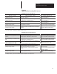
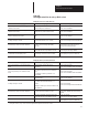
The selected port should be set as follows:
MODEM CONTROL (ENABLE/DISABLE) = DISABLE.
9600 BITS PER SECOND (YES/NO) = YES.
8 BITS NO PARITY (YES/NO) = YES.
XON/XOFF (ENABLE/DISABLE) = DISABLE.
RS422 (YES/NO) = YES.
RECEIVE MATRIXING (ENABLE/DISABLE) = DISABLE.
BYTE SWAPPING (ENABLE/DISABLE) = ENABLE.
BINARY DATA NO CONVERSIONS (YES/NO) = YES.
HDR/TLR ON OUTPUT (ENABLE/DISABLE) = ENABLE.
HEADER BYTE LENGTH (DEC 0 . . . 4) = 0.
HEADER DATA [0] (HEX 0 . . .ff) = 0.
HEADER DATA [1] (HEX 0 . . .ff) = 0.
HEADER DATA [2] (HEX 0 . . .ff) = 0.
HEADER DATA [3] (HEX 0 . . .ff) = 0
.
TRAILER BYTE LENGTH (DEC 0 . . .4) = 1.
TRAILER DATA [0] (HEX 0 . . .ff) = 0.
TRAILER DATA [1] (HEX 0 . . .ff) = d.
TRAILER DATA [2] (HEX 0 . . .ff) = 0.
TRAILER DATA [3] (HEX 0 . . .ff) = 0
MAX DATA BYTE LENGTH (DEC 0 . . . 124) = 0.
MIN DATA BYTE LENGTH (DEC 0 . . . 124) = 0
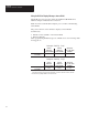
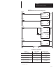
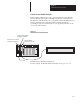
The program consists of two rungs:
• Rung 0 initiates the block transfer of data to the Flexible Interface
Module. N7:00 is the data file with the DL50 message. In this example,
I:2/0 is the input which triggers the message.
• Rung 1 reads command responses from the Flexible Interface Module.
You can delete this rung if the Flexible Interface Module is configured
with handshake data disabled and the DL50 is set for Simplex Protocol.
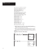
Figure 6.3
Ladder Diagram: Flexible Interface Module Example
ONS
BLOCK TRNSFR WRITE
BTW
Rack 00
Group 0
Module 0
Control Block N7:5
Data file N7:100
Length 0
Continuous N
EN
DN
ER
Rung 2:0
BLOCK TRNSFR READ
BTW
Rack 00
Group 0
Module 0
Control Block N7:0
Data file N7:200
Length 0
Continuous N
EN
DN
ER
Rung 2:1