
INSTALLATION MANUAL User Manual

Chapter 3
Configuring the DL50
3–3
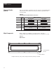
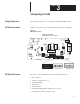
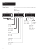
If the “slave mode” has been selected, switches S1-1 through S1-8 define an
address for the DL50 display. The values for each switch are illustrated
below. The address of the DL50 is the sum of the values for all of the
switches (1 - 8) that are turned on.
Note: SLAVE MODE is always selected for normal operation.
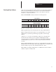
Slave Address
Switch Number 1 2 3 4 5 6 7 8
Value (decimal) 128 64 32 16 8 4 2 1
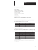
Addressing Example
Switch Number 1 2 3 4 5 6 7 8
Switch Position ON OFF ON OFF OFF ON ON OFF
The above example address = 128 + 32 + 4 + 2 = 166.
Note: Appendix D provides switch positions for all possible addresses.
Note: A display with a slave address of 127 (Simplex Protocol) or 255
(Duplex Protocol) will accept all messages regardless of the message
address.
Certain other slave addresses are not valid for DL50 displays when
connected as slaves to a DL20 or DL40 master. The illegal DL20/DL40
decimal addresses are: 0, 4, 6, 7, 13, 16, 18, 20, 22, 43, 45, 48-57, and
128-255.
When multiple DL50 displays are placed on one RS-485 link, more than one
DL50 can have the same address when using Simplex Protocol. DL50’s with
the same address respond to all commands addressed to them.
Note: DL50’s operating in Duplex Protocol cannot have the same address
with the exception of address 255.
Selectin
g
Slave Add
r
ess