Allen-Bradley Dataliner DL50 Series Message Display (Cat. No.
Important User Information Solid state equipment has operational characteristics differing from those of electromechanical equipment. “Safety Guidelines for the Application, Installation and Maintenance of Solid State Controls” (Publication SGI-1.1) describes some important differences between solid state equipment and hard-wired electromechanical devices.
Table of Contents Dataliner DL50 Series User Manual Using This Manual Chapter 1 Chapter Objectives . . . . . . . . . . . . . . . . . . . . . . . . . . . . . . . . . . . . . . . . . Overview of this Manual . . . . . . . . . . . . . . . . . . . . . . . . . . . . . . . . . . . . Intended Audience . . . . . . . . . . . . . . . . . . . . . . . . . . . . . . . . . . . . . . . . . Conventions Used . . . . . . . . . . . . . . . . . . . . . . . . . . . . . . . . . . . . . . . . . Attention Symbol . . . . . . . . .
Table of Contents Dataliner DL50 Series User Manual Installing the DL50 (continued) Serial Communications Wiring Recommendations . . . . . . . . . . . . . . . . . . . . . . . . . . . . . . . . . . . European Union Directive Compliance . . . . . . . . . . . . . . . . . . . . . . . . . Grounding Recommendations . . . . . . . . . . . . . . . . . . . . . . . . . . . . . . . . Connecting Power . . . . . . . . . . . . . . . . . . . . . . . . . . . . . . . . . . . . . . . . . Annunciation Relay Connections . .
Table of Contents Dataliner DL50 Series User Manual Serial Communications (continued) Slave Mode Operation / Examples Bootstrap Mode Duplex Protocol . . . . . . . . . . . . . . . . . . . . . . . . . . . . . . . . . . . . . . . . . . . Field 1: Control Byte . . . . . . . . . . . . . . . . . . . . . . . . . . . . . . . . . . . . Field 2: ASCII Text or Special Control Characters . . . . . . . . . . . . . Field 3: Slave Address . . . . . . . . . . . . . . . . . . . . . . . . . . . . . . . . . . .
Table of Contents Dataliner DL50 Series User Manual Troubleshooting and Maintenance Chapter 8 Specifications Chapter 9 Display Descriptions Appendix A ASCII Character Set Appendix B Dimensions Appendix C Serial Address Settings Appendix D Internal Wiring Diagrams Appendix E Checksum Calculations Appendix F Character Attribute Worksheet European Union Directive Compliance Glossary Appendix G Index Chapter Objectives . . . . . . . . . . . . . . . . . . . . . . . . . . . . . . . . . . . . .
Chapter A–B 1 Using This Manual Chapter Objectives Read this chapter to familiarize yourself with the rest of the manual. You will learn about: • • • • • Overview of this Manual Contents of this manual Intended audience Conventions used Warnings and cautions Related publications Table 1.
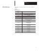
Chapter 1 Using This Manual Intended Audience Only qualified service personnel may configure and install Dataliner DL50 Message Displays. No operator access to internal configuration switches or connectors is required. Conventions Used The following conventions are used: • The Catalog No. 2706ĆF11J, ĆF11JC, ĆF21J, and ĆF21JC DL50 Series Marquee Message Displays are referred to as the DL50.
Chapter 1 Using This Manual Related Publications Table 1.B lists some publications that you may require for additional reference. Table 1.B Related Publications Publication / Catalog Number 2706-800 Dataliner DL10 Series User’s Manual 2706-814 Dataliner DL20 Series User’s Manual Title 2706-808 Dataliner DL40 Series Message Display User’s Manual Dataliner DL40 Series Offline Programming Software 1771-6.5.13 ASCII I/O Module (Catalog No. 1771-DA) User’s Manual 1771-6.5.
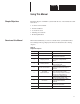
Chapter A–B 2 Introduction to the DL50 Chapter Objectives This chapter describes the basic features, functions, and operating modes of the DL50. Overview The DL50 displays high visibility messages. Messages can be viewed from up to 240 feet (73.2 meters) away. This high visibility allows messages (fault, status, etc.) to be seen and responded to quickly. Messages on the 2706-F11J and -F21J units are displayed in red.
Chapter 2 Introduction to the DL50 Character Number and Size The size and number of characters depends on the size of the DL50 display. Select the size of the characters based upon visibility requirements and message length Table 2.A DL50 Display:Color; Number and Size of Characters Major Components Catalog No. Display Color 2706-F11J Red 2706-F11JC Red, Green, Amber 2706-F21J Red 2706-F21JC Red, Green, Amber Number of Characters 4.8 inch (122 mm) 1 line of 10 2.
Chapter 2 Introduction to the DL50 Figure 2.2 Major Components Conduit Openings ➈ Catalog No. 2706-F11J, -F11JC ➈ Conduit Openings Installation / Diagnostic Information Label Processor Board ➃ Power Connections ➂ Relay Output Connections RESET ➇ RS-485 Port Connections RESET ➆ RS-232 Port Connections ➄ Reset Button ➅ Configuration DIP Switches Catalog No.
Chapter 2 Introduction to the DL50 Descriptions ➀ OVERTEMP Indicator The LED on the upper right hand corner of the display indicates if the DL50 is in the Reduced Brightness Mode. This LED is normally off. If the temperature inside the DL50 reaches its internal operating limit, the DL50 will enter the Reduced Brightness Mode, and this LED will begin flashing. If the LED is on steady, the DL50 is in an automatic shutdown mode. The ambient temperature must be reduced to continue operation.
Chapter 2 Introduction to the DL50 ➅ Configuration DIP Switches Use these DIP switches to select: • • • • • • • • Slave Address Protocol (Simplex or Duplex) Duplex Checksum (On or Off) Character Height Default Color (TriĆcolor displays) Baud Rate Mode Select Hardware Type Chapter 3 provides a complete description of these switches. ➆ RS-232 Port Connections The RS-232 communications port allows point-to-point communications between the DL50 and a host at distances of up to 50 feet (15.2 meters).
Chapter 2 Introduction to the DL50 Operating Modes The DL50 operates in one of three modes: • Slave Mode. (Chapter 6) Slave mode is the normal operating mode of the DL50. In this mode the DL50 will accept packets of data from either the RS-232 or RS-485 port. The DL50 supports both simplex and duplex communications. • Diagnostic Mode. (Chapter 8) Use this mode if the DL50 is not functioning properly. The diagnostic mode helps isolate faults down to a serviceable component. • Bootstrap Mode.
Chapter 2 Introduction to the DL50 Communications Overview The DL50 has both an RS-232 and an RS-485 communications port. Figure 2.3 illustrates some of the most common point-to-point and network applications. Figure 2.
Chapter 2 Introduction to the DL50 Figure 2.3 Communications Overview (continued) Host Programmable Controller, Computer or Workstation RS-232 Interface DL50 DISPLAY Host Programmable Controller, Computer or Workstation RS-232 Interface RS-232 RS-485 Converter RS-485 RS-485 DL50 DISPLAY Host Programmable Controller To Other Dataliner Displays RS-485 DL50 DISPLAY To Other Dataliner Displays RS-485 DL50 DISPLAY RS-485 DL50 DISPLAY RS-232 BASIC Module (Catalog No.
Chapter A–B 3 Configuring the DL50 Chapter Objectives This chapter describes how to configure the DL50 using DIP switches. DIP Switch Locations Figure 3.1 shows the location of the DIP switches used for configuration. Figure 3.1 DIP Switch Locations RESET DL50 Processor Board (Refer to Figure 2.
Chapter 3 Configuring the DL50 Setting Switches Figure 3.2 illustrates how to select the various functions with DIP switches. Figure 3.
Chapter 3 Configuring the DL50 Selecting Slave Address If the “slave mode” has been selected, switches S1-1 through S1-8 define an address for the DL50 display. The values for each switch are illustrated below. The address of the DL50 is the sum of the values for all of the switches (1 - 8) that are turned on. Note: SLAVE MODE is always selected for normal operation.
Chapter 3 Configuring the DL50 Selecting Protocol The DL50 communicates with a host device using strings of ASCII characters. The DL50 can communicate using one of two protocols: • Simplex. When simplex protocol is selected, the DL50 does not provide any response to a master device. The master sends out packets of data, each containing message text and other information. The DL50 uses this information to display messages. • Duplex.
Chapter 3 Configuring the DL50 Table 3.A Character Height With Auto-Select Enabled 1 Text is Displayed On This Line 1 Auto-Select Character Height 2.1 inches (53.4 mm) ➀ 2 2 2.1 inches (53.4 mm) 3 1➁ 4.8 inches (121.9 mm) 4 ➂ Not Applicable Line Number From Master 30 ➀ ➁ ➂ ➃ Selecting Baud Rate 1&2➃ 2.1 inches (53.4 mm) Line height is for multiple line messages. If a one line message is received, line height is 4.8 inches (121.9 mm). Only a 4 line Dataliner can send out line number 3.
Chapter 3 Configuring the DL50 Selecting Operating Mode Slave mode is the standard operating mode for the DL50. If the DL50 is not operating properly, the Diagnostic mode will help isolate the problem (refer to Chapter 8). Operating Mode Switches Enabling/Disabling Checksum Mode Switch Number S2-6 Switch Number S2-7 Slave Mode OFF OFF Diagnostics Mode OFF ON Reserved ON OFF Reserved ON ON This switch enables and disables the checksum for duplex protocol messages.
Chapter 3 Configuring the DL50 The DL50 loads DIP switch settings on power-up and when the RESET button is pressed. The RESET switch is located on the left side of the processor board (refer to Figure 3.3). Figure 3.3 Reset Switch RESET DL50 Reset RESET Reset Switch Press this momentary switch to begin the reset. The DL50 will enter the self-test mode and display power-up status information as shown in Figure 3.4.
Chapter 3 Configuring the DL50 Figure 3.4 DL50 Self-Test Sequence Protocol Text Mode Slave Address SLAVE ADDR: XXXX SUB-ADDR: XXXX Self Test Baud Rate SELF TEST: PASS Baud Rate: XXXXX Protocol: DUPLEX Checksum: ON ON, OFF DL50 Type Firmware Version Simplex or Duplex Mode 300, 1200, 9600, 19200 Protocol: SIMPLEX Mode: Small Text DL50 F11JC TRI-COLOR Firmware Ver: X.
Chapter A–B 4 Installing the DL50 Chapter Objectives This chapter describes how to mount the DL50. Instructions are also provided on connecting the DL50 to communications lines and power source. Mounting Dimensions Figure 4.1 shows the mounting dimensions of the displays. Figure 4.1 Mounting Dimensions 3/4 inches (19 mm) 19 3/16 inches (487 mm) 19 3/16 inches (487 mm) Catalog No. 2706-F11J, -F11JC 10 11/16 inches (271 mm) 40.4 inches (1026.2 mm) 13/16 inches (21.
Chapter 4 Installing the DL50 Mounting Methods There are four methods of mounting the displays • • • • Flush surface mount using the angle brackets supplied with the DL50. Surface mount using optional adjustable brackets (Catalog No. 2706-NJ3) Back-to-Back using adjustable brackets (Catalog No. 2706-NJ3). Chain suspended (individually or back-to-back) ! ATTENTION: The displays are heavy. Proper installation techniques are necessary to avoid injury from a falling display.
Chapter 4 Installing the DL50 Wall Mounting- Using Angle Brackets Mount the DL50 directly to a wall using screws and wall anchors as shown in Figure 4.2. Figure 4.
Chapter 4 Installing the DL50 Wall Mounting- Using Adjustable Brackets (Catalog No. 2706-NJ3) Mount the DL50 to a wall using Adjustable Brackets (Catalog No. 2706-NJ3) as shown in Figure 4.3. Note: Catalog No. 2706-NJ3 contains 2 pairs of brackets. You will need 2 pairs of brackets to mount Catalog No. 2706-F11J, -F11JC and 4 pairs of brackets to mount Catalog No. 2706-F21J, -F21JC. Figure 4.3 Wall Mounting With Adjustable Brackets Mounting Bracket (Catalog No.
Chapter 4 Installing the DL50 Chain Suspension The DL50 can be suspended from a pair of chains. Each chain must be capable of supporting: 400 pounds (182 kilograms) for Catalog No. 2706-F11J, -F11JC 750 pounds (341 kilograms) for Catalog No. 2706-F21J, -F21JC ! ATTENTION: Make sure the supporting chain meets the minimum specifications listed above. Failure to follow this warning could result in damage to the display and personal injury. Figure 4.
Chapter 4 Installing the DL50 Back to Back Mounting Mount two DL50 displays back-to-back with or without mounting brackets (Catalog No. 2706-NJ3). These mounting methods are illustrated in Figure 4.5 and Figure 4.6. The chains attached to each display must be able to support: 400 pounds (182 kilograms) for Catalog No. 2706-F11J, -F11JC 750 pounds (341 kilograms) for Catalog No. 2706-F21J, -F21JC The chain supporting both displays must be able to support: 800 pounds (364 kilograms) for two Catalog No.
Chapter 4 Installing the DL50 Figure 4.5 Back to Back Mounting Without Adjustable Brackets Chain Must Be Able To Support: 800 pounds (364 kg) when hanging two Catalog No. 2706-F11J, -F11JC Displays 1500 pounds (682 kg) when hanging two Catalog No. 2706-F21J, -F21JC Displays Chains Must Be Able To Support: 400 pounds (182 kg) when hanging two Catalog No. 2706-F11J, -F11JC Displays ÊÉ Ê DL50 ÊÉ 750 pounds (341 kg) when hanging two Catalog No.
Chapter 4 Installing the DL50 Figure 4.6 Back to Back Mounting With Adjustable Brackets Chain Must Be Able To Support: 800 pounds (364 kg) when hanging two Catalog No. 2706-F11J, -F11JC Displays 1500 pounds (682 kg) when hanging two Catalog No. 2706-F21J, F21JC Displays Chains Must Be Able To Support: 400 pounds (182 kg) when hanging two Catalog No. 2706-F11J, -F11JC Displays 750 pounds (341 kg) when hanging two Catalog No.
Chapter 4 Installing the DL50 Wiring Recommendations Careful wire routing helps cut down on electrical noise. To reduce electrical noise, the DL50 should be connected to its own branch circuit. (See the next section for power requirements in the European Union or EFTA regions.)The input power source should be protected by a fuse or circuit breaker rated at no more than 15 Amps. Route incoming power to the DL50 by a separate path from the communication cables.
Chapter 4 Installing the DL50 Grounding Recommendations Grounding is an important safety measure in electrical installations. Grounding also helps eliminate the effects of noise due to Electromagnetic Interference (EMI). An authoritative source on grounding requirements is the National Electrical Code published by the National Fire Protection Association of Boston, Massachusetts.
Chapter 4 Installing the DL50 1. Connect ground wire to the chassis grounding terminal. Then verify that the factory installed earth ground wire is connected between the chassis PE (Protective Earth) terminal and the earth ground terminal on the power input connector. Note: If the power lines enter the left side of the display, route the AC lines through the cable guides on the upper part of the display. Route the communication lines through the cable guides on the bottom half of the display. 2.
Chapter 4 Installing the DL50 RS-232 Connections The RS-232 interface allows connection of a single DL50 display, with a maximum recommended cable length of 50 feet Figure 4.9 shows the location of the DL50’s RS-232 port terminals. The terminals are labeled: RS-232 Connection Terminals Terminal Number* Label Definition 1 T Transmit Line 2 R Receive Line 3 GND Signal Ground * Pin #1 is on top. RESET Figure 4.
Chapter 4 Installing the DL50 Figure 4.10 shows a typical connection between a host device RS-232 port and the DL50 display. The DL50 display is considered a “DTE” (Data Terminal Equipment) device. The connection diagram assumes that the RS-232 port of the host device is also a “DTE” type, as most are. If instead it is a “DCE” (Data Communications Equipment) type, you should interchange the wires on pins 2 and 3.
Chapter 4 Installing the DL50 RS-485 Connections The RS-485 interface has these advantages over the RS-232 • Improved noise immunity. • DL50 displays can be a distance of up to 4000 feet (1200 m) from the host device. • Up to 32 devices can be connected directly to the RS-485 port of the host controller. Up to 100 DL50 displays can be addressed when line drivers are used. Figure 4.11 shows the location of the DL50’s RS-485 port terminals.
Chapter 4 Installing the DL50 Figure 4.12 shows a typical connection between a host device RSĆ485 port and DL50 displays. We recommend that you use Belden 9842 cable. Note that pin or terminal numbers are not shown for the host device. This is because the terminal numbers vary for different products. For actual pin numbers, refer to the appropriate host device product literature. We recommend that you connect the shield to ground at one end only, as shown. Figure 4.
Chapter 4 Installing the DL50 Connection to DL20/DL40 “Master” Displays As previously described, a DL50 display can be connected to the RS-232 or RS-422 port of a DL20 display or the RS-485 port of a DL40 display (Master). When this type of configuration is used, all messages are stored in the Master DL20/DL40 displays. All the host controller is required to do is trigger a particular message stored in the Master DL20/DL40 display.
Chapter 4 Installing the DL50 Note: If noise problems occur between a DL20 master display and a slave DL50 display (RS-232), we recommend that you connect the shield of the communication cable to chassis ground at both ends. The earth ground for each device must be the same potential to insure that ground currents do not flow. Connect the slaves to the master using Belden 9842 cable. Figure 4.14 shows the DL40 to DL50 wiring connections. Figure 4.
Chapter 4 Installing the DL50 Connection as Slave to DL20 “Master” RS-232 Port It is also possible to use the RS-232 output of the DL20 to connect to one DL50 slave, however the distance limitation is 50 feet. These connections are shown in Figure 4.15. Figure 4.
Chapter 4 Installing the DL50 Connection to Personal Computers The DL50 display may be connected to personal computers through an RS-232 port. Either Simplex or Duplex protocol may be used in applications with a personal computer as host. • For single-point connections of 50 feet or less, the DL50 RS-232 port may be connected directly to the personal computer RS-232 port. See Figure 4.16. Figure 4.
Chapter 4 Installing the DL50 Figure 4.17 Personal Computer to DL50 RS-485 Port(s) DL50 RS-485 TERMINALS EGND 1 SHLD 2 3 4 5 COM + – TERM NOTE: CONNECT SHIELD TO EGND AT ONE NODE ONLY Computer RS-232 port DB-9 Connector Black Box LD485A-MP RxB RxA TxB Signal Ground 5 Transmit 3 Receive 2 2 3 7 TxA 6 Shield DB-25 RS-485 RS-232 Note: Allen-Bradley 2706-NC15 cable will connect directly from a personal computer serial port (male DB-9) to the Black Box LD485A-MP.
Chapter 4 Installing the DL50 Connection to Allen-Bradley Programmable Controllers Most Allen-Bradley Programmable Logic Controllers (PLCs) provide a variety of methods to interface RS-232 or RS-485 devices. They include the: Mini PLC-2 Mini PLC-2/15, -2/05, etc. PLC-2/20 (1772-LP1, -LP2) PLC-2/30 (1772-LP3) PLC-3 PLC-3/10 PLC-5 Family SLC 500 Family The most common means of providing serial interfaces for the above Programmable Controllers include the following optional modules: BASIC Module- Catalog No.
Chapter 4 Installing the DL50 BASIC Module Catalog No. 1771-DB Catalog No. 1746-BAS The Allen-Bradley BASIC Modules (Catalog No. 1771-DB and Catalog No. 1746-BAS) provide a cost-effective and efficient serial interface to Allen-Bradley PLC and SLC controllers. The BASIC Modules store all messages in battery-backed RAM or EPROM. The modules can be programmed to transmit these messages along with status or variable data from the programmable controller.
Chapter 4 Installing the DL50 Peripheral Communications Module Catalog No. 1771-GA The Peripheral Communications Module (Catalog No. 1775-GA) is only applicable to Allen-Bradley PLC-3 Family Programmable Controllers. The module plugs directly into the PLC-3 chassis. It has several serial ports and is capable of performing many unique tasks at one time for a PLC-3 System. The Peripheral Communications Module supports RS-232 serial port specifications. Figure 4.
Chapter 4 Installing the DL50 ASCII I/O Module Catalog No. 1771-DA The ASCII I/O Module (Catalog No. 1771-DA) provides a serial interface for almost all Allen-Bradley programmable controllers. It can be plugged into any slot of a standard 1771 local or remote I/O rack. The ASCII I/O Module has no memory or programming language. All DL50 display messages would be stored in the programmable controller’s memory. Figure 4.20 shows how to connect the RS-232 port of the DL50 to a ASCII I/O Module.
Chapter 4 Installing the DL50 Flexible Interface Module Catalog No. 2760-RB Use the Flexible Interface Module with either the Catalog No. 2760-SFC1 or 2760-SFC2 cartridge with Dumb Terminal (DT) protocol. Multidrop up to 31 DL50’s on each of the three communications ports on the module. Figure 4.21 shows how to connect the RS-485 port of the DL50 to a Flexible Interface Module RS-422 port. Figure 4.
Chapter A–B 5 Serial Communications Chapter Objectives This chapter describes how to communicate with the DL50 using a simple ASCII string format. The DL50 supports both simplex and duplex communications protocols. Each will be addressed in this chapter. Protocols Simplex Communications- In this protocol, the DL50 does not provide any responses to the master device. The DL50 receives message packets from the master device and uses this information to display text.
Chapter 5 Serial Communications Simplex Protocol The simplex data packet consists of 6 data fields as shown below: Field 1 Field 2 Optional Control ASCII Text or Special Control Byte Characters 1 Byte 0-250 Bytes Field 3 Optional Display Mode 1 Byte Field 4 Field 5 Slave Address 1 Byte Field 6 Line Number Carriage Return 1 Byte 1 Byte Note: Simplex protocol is compatible with Allen-Bradley DL20 and DL40 message displays.
Chapter 5 Serial Communications Simplex Protocol (continued) Field 3: Optional Display Mode This optional field indicates how the message text is to be displayed. If this optional byte is not present, the Line Number (field 5) determines the display mode. The following control characters are used: Table 5.
Chapter 5 Serial Communications Simplex Protocol (continued) Field 3: Optional Display Mode (continued) Special Control Characters When operating in the slave mode, the DL50 will recognize the following special control characters: • Ctrl F [FLASH] The Ctrl F (decimal 6) control character causes the DL50 to toggle between flashing and non-flashing characters. Text which is between two Ctrl F characters will flash, all other characters will be non-flashing.
Chapter 5 Serial Communications Simplex Protocol (continued) Field 4: Slave Address The slave address is a single byte field that can be any value from 1- 255, except for 6, 13,16, and 18. When connecting a DL50 to a DL20/DL40 master, the illegal decimal addresses are: 0, 4, 6, 7, 13, 16, 18, 20, 22, 43, 45, 48-57, and 128-255. A display with an address of 127 will accept all message packets regardless of the address on the packet.
Chapter 5 Serial Communications Simplex Protocol (continued) Table 5.E Line Number Effect On Catalog No. 2706-F21J, -F21JC Display Mode Line Number Field 5 (Decimal) 2.1 Inch Text 1 2 3 4 30 Text Displayed On Line Number: Character Size (Inches) 2.1 2.1 2.1 2.1 2.1 4.8 Inch Text 1 2 3 4 30 1 (1st 20 Characters) 1 (2nd 20 Characters) 2 (1st 20 Characters) 2 (2nd 20 Characters) 1 and 2 ➀ 1➁ Line Ignored Line Ignored Line Ignored 1➁ 4.8 Not Applicable Not Applicable Not Applicable 4.
Chapter 5 Serial Communications Simplex Protocol (continued) Clearing Lines of Text • You can either send a message packet with a control byte (field 1) that has a Ctrl-C (decimal 3) value, or • You can send a message packet with the following format: Field 1 Field 2 Slave Address 1 Byte Field 3 Line Number Carriage Return 1 Byte 1 Byte The line number in the message packet specifies which line(s) to clear: ASCII Character Decimal Value Functi
Chapter 5 Serial Communications Duplex Protocol Duplex Communications- In this Protocol, the DL50 provides a response to each command it receives. The response includes data checking bytes (Checksum) and a handshake byte (ACK/NAK). The DL50 receives message packets from the master device, transmits data checksum/handshake bytes back to the master, and uses the message data to display text.
Chapter 5 Serial Communications Duplex Protocol (continued) A control byte containing Ctrl-L (decimal 12) indicates that the DL50 is being initialized for the bootstrap mode. In this mode the DL50 will be idle, waiting for the host to transmit a firmware update (refer to Chapter 7). Field 2: ASCII Text or Special Control Characters This field contains the ASCII characters (up to 250) that are to be displayed by the DL50 or sent to the message buffer.
Chapter 5 Serial Communications Duplex Protocol (continued) Field 6: Message Attributes This three byte field specifies how a message is displayed. The three bytes specify: Byte 1 Byte 2 Byte 3 Display Mode Text Height Display Speed Relay Control Reserved Display Mode / Speed The first byte of the Message Attributes field specifies display mode / display speed. The first five bits indicate display mode and the last three bits indicate the display speed.
Chapter 5 Serial Communications Duplex Protocol (continued) Field 6: Message Attributes (continued) Special Control Characters When operating in the slave mode, the DL50 will recognize the following special control characters: • Ctrl F [FLASH] The Ctrl F (decimal 6) control character causes the DL50 to toggle between flashing and non-flashing characters. Text which is between two Ctrl F characters will flash, all other characters will be non-flashing.
Chapter 5 Serial Communications Duplex Protocol (continued) Field 6: Message Attributes (continued) Table 5.I Bits 5 through 7 of the Message Attribute 1st Byte Function Fastest Display Fast Display Bits 7 5 ➀ 1 0 0 1 0 1 Decimal Value ➁ 128 160 Slow Display 1 1 0 192 Slowest Display 1 1 1 224 ➀ Bit 7 is always set to 1. ➁ Add decimal values for all bits within a byte to determine value of the entire byte.
Chapter 5 Serial Communications Duplex Protocol (continued) Field 6: Message Attributes (continued) Third Byte Message Attributes- The third byte of the Message Attributes field is reserved for future enhancements.
Chapter 5 Serial Communications Duplex Protocol (continued) Response From the DL50 To every command the DL50 successfully receives, the DL50 will provide a response. The response packet has the following format Field 1 ACK or NAK 1 Byte Field 2 Field 3 Status Byte 1 Byte Checksum 3 Bytes 1. If the DL50 Display successfully received the message packet, and is ready to process it, the DL50 sends an acknowledge response (ACK 6 decimal). In this case, the contents of the status byte are irrelevant. 2.
Chapter A–B 6 Slave Mode Operation / Examples Chapter Objectives This chapter describes how to operate the DL50 in the slave mode. The slave mode is the normal operating mode of the DL50. In order to show the operation of the DL50, this chapter contains example messages and host programs. Slave Mode Operation To operate the DL50 in the slave mode, perform the following steps: 1. Install the DL50 as described in Chapter 4. 2. Configure the DL50 using the configuration DIP switches as shown in Figure 3.
Chapter 6 Slave Mode Operation / Examples Example 1 (Simplex Protocol) Command Function: Display message shown below on all DL50 message displays with an address of 42.
Chapter 6 Slave Mode Operation / Examples Example 2 (Duplex Protocol) Command Function: Display message shown below on all DL50 message displays. Motor ON The command specifies message attributes of roll in display mode, fast display speed, 4.8 inch text, and annunciation relay on. Address 255 specifies that the message is displayed on all DL50s.
Chapter 6 Slave Mode Operation / Examples Example 3 (Relay On) Command Function: Energize annunciation relay on DL50 with an address of 150.
Chapter 6 Slave Mode Operation / Examples Example 5 (Send 2-Line Message) Command Function: Display message as shown below on lines 1 and 2 of all DL50s using the line number field value of 30. . Se que nc e Er r or : R OB OT N OT P OS I T I O N E D The command is written for a Catalog No. 2706-F11J or -F11JC display. Address 127 specifies that the message is displayed on all DL50s. The word “NOT” in the message will flash.
Chapter 6 Slave Mode Operation / Examples Programming Examples The following are examples showing how some of the most common hosts would be programmed to send messages to a slave DL50. Using the DL50 to Display Messages from a DL20 Chapter 4 illustrates the connections between the DL50 and a DL20 Series Dataliner. Note: You must set the DL50 for Simplex protocol when communicating with a DL20.
Chapter 6 Slave Mode Operation / Examples Table 6.A Application Hints for using a DL20 as host Displaying 2.1 Inch (53.3 mm) Characters DL20 Message Type How Message Appears On DL50 DL50/DL20 Application Notes “Line 1 Only”or “Line 2 Only” message 20 characters on the DL20 Message appears as a Line 1 or Line 2 message on the DL50 with up to 20 characters.➀ DL50: 2.1 Inch characters or auto-select. DL20: Line used attribute.
Chapter 6 Slave Mode Operation / Examples Using the DL50 to Display Messages from a DL40 The DL50 can receive message data from a Bulletin 2706 DL40 Series Dataliner. Chapter 4 illustrates the connections. Note: You must set the DL50 for Simplex protocol when communicating with a DL40.
Chapter 6 Slave Mode Operation / Examples Table 6.B DL40 Application Hints for using a DL40 as host Displaying 2.1 Inch (53.3 mm) Characters DL40 Message Type How Message Appears On DL50 DL50/DL40 Application Notes “Line 1 Only”or “Line 2 Only” message 20 characters on the DL40 Message appears as a Line 1 or Line 2 message on the DL50 with up to 20 characters.➀ “Line 1 Only”or “Line 2 Only” message > 20 characters on the DL40 Appears as a Line 1 or Line 2 message on the DL50 DL50: 2.
Chapter 6 Slave Mode Operation / Examples Updating Embedded Variables from a DL20 or DL40 Use the following guidelines when updating embedded variable data in DL50 messages from a DL20 or DL40 Dataliner. • For a DL20, update variables using a sequencer to strobe the high and low bytes of each variable as well as the message number (as described in DL20 User Manual). A baud rate of 9600 is recommended. • For a DL40, a baud rate of 9600 is recommended.
Chapter 6 Slave Mode Operation / Examples Figure 6.1 PLC-5 Embedded Variable Wait Time Adjustment Rung 2:0 +TON TIMER ON DELAY EN Timer T4:0 Time base 0.01 Preset See table below Accum 3 Rung 2:1 +TON TIMER ON DELAY Timer Time base Preset Accum Rung 2:2 DN EN T4:1 0.01 1000 256 DN +MOV MOVE Source 1000 Dest 0:010 1000 +MOV MOVE Source Dest Rung 2:3 T4:1.
Chapter 6 Slave Mode Operation / Examples DL50 BASIC Alarm Programming Example This example is for Catalog No. 2706-F11J, -F11JC. Use it as a guide in creating your own alarm programs. The program determines which alarm(s) are current and the priority in which they are displayed. The program is compatible with Microsoft QuickBasic and IBM GW BASIC / BASIC A. Here is a quick summary of the program: Lines 5 to 10 initialize the computer communications port for the DL50.
Chapter 6 Slave Mode Operation / Examples 1025 LN=48: ADDRESS = 1: M$ = ’’ ’’: REM THIS TURNS ON THE DL50‘s RELAY 1026 RETURN 1030 LN=49: ADDRESS = 127: M$ = ’’ ’’: REM THIS TURNS OFF THE DL50‘s RELAY 1031 RETURN 1035 LN=50: ADDRESS = 127: M$ = ’’ ’’: REM THIS CLEARS THe DL50 DISPLAY 1036 RETURN 2000 RETURN 4000 REM LINE 4000-6000 DETERMINE IF ANY ALARMS ARE CURRENT AND WHICH 4001 REM ONE HAS PRIORITY 4002 REM 4030 INPUT “Alarm No.
Chapter 6 Slave Mode Operation / Examples 1771–DB BASIC Module Simplex Example The following is an example of print statement using a BASIC Module (Catalog No. 1771-DB) as a host. The example assumes that the DL50 slave has an address of 1.
Chapter 6 Slave Mode Operation / Examples Flexible Interface Module Example In this example, a PLC-5/15 is used to send a message through a Flexible Interface Module (Catalog No. 2760-RB) using RS-422 communications. The RS-422 communications port is compatible with the DL50 RS-485 port. Figure 6.2 illustrates the setup. The Simulator Module (Catalog No. 1771-SM) provides the external inputs, in your application this may be any of a variety of I/O modules. Figure 6.
Chapter 6 Slave Mode Operation / Examples The selected port should be set as follows: MODEM CONTROL (ENABLE/DISABLE) = DISABLE. 9600 BITS PER SECOND (YES/NO) = YES. 8 BITS NO PARITY (YES/NO) = YES. XON/XOFF (ENABLE/DISABLE) = DISABLE. RS422 (YES/NO) = YES. RECEIVE MATRIXING (ENABLE/DISABLE) = DISABLE. BYTE SWAPPING (ENABLE/DISABLE) = ENABLE. BINARY DATA NO CONVERSIONS (YES/NO) = YES. HDR/TLR ON OUTPUT (ENABLE/DISABLE) = ENABLE. HEADER BYTE LENGTH (DEC 0 . . . 4) = 0. HEADER DATA [0] (HEX 0 . . .ff) = 0.
Chapter 6 Slave Mode Operation / Examples This is what the data files look like: Address 0 1 N7:100 \00\26 \05\01 N7:110 50 __ 2 3 4 5 6 7 8 9 _R B_ Mo du le _t o_ DL \05\01 DL50 Line No.
Chapter 6 Slave Mode Operation / Examples PLC-5 Channel 0 Simplex Example This example demonstrates how to use the RS232 Channel 0 of supporting members of the Allen-Bradley PLC-5 family to trigger a Dataliner DL50 display. In the example, a counter is used to simulate changing variable data, which could be a motor speed or a temperature. This will demonstrate how variable data may be incorporated into messages.
Chapter 6 Slave Mode Operation / Examples PLC String Variables For this example, processor memory file #12 is set up as a string file which contains the parts needed to form a message packet for a DL50 in Simplex mode. Table 6.D has the variables for any Simplex mode communication, and Table 6.E shows the strings for this example. Table 6.
Chapter 6 Slave Mode Operation / Examples Ladder Logic The ladder logic builds a string from all the parts and sends it out to the DL50 via channel 0. Messages sent to the DL50 by the PLC must observe the required inter-message delays described in Table 5.F. Note: Use a timer to avoid sending continuous messages. Figure 6.4 Ladder Diagram: Channel 0 Simplex Example Rung 2:0 A free running timer used to trigger a variable counter and create a delay for message timing.
Chapter 6 Slave Mode Operation / Examples | |+AWT––––––––––––––––––––+ | | | ++ASCII WRITE +–(EN)+ | | |Channel 0| | | |Source MSG_SEND+–(DN) | | |Control R6:0| | | |String length 0+–(ER) | | |Characters sent 15| | | +–––––––––––––––––––––––+ | Rung 2:3 The counter is reset when it is done.
Chapter 6 Slave Mode Operation / Examples PLC-5 Channel 0 Duplex Example The following example demonstrates how to use the RS232 Channel 0 of supporting members of the Allen-Bradley PLC-5 family to trigger a DL50 Dataliner display, running in Duplex mode with checksum disabled. In this example a counter is used to simulate changing variable data, which could be a motor speed or a temperature. This will demonstrate how variable data can be incorporated into messages.
Chapter 6 Slave Mode Operation / Examples PLC String Variables For this example, processor memory file #12 is set up as a string file which contains the parts needed to form a message packet for a DL50 in Duplex mode. Table 6.G has the variables for any Duplex mode communication, and Table 6.H shows the strings for this example. Table 6.
Chapter 6 Slave Mode Operation / Examples The contents of these strings must be assigned using the PLC off-line programming software (6200). Control code values are entered into the strings by using a forward slash followed by two hexadecimal digits. See Appendix B, which has hexadecimal values for all ASCII and extended ASCII characters. Table 6.
Chapter 6 Slave Mode Operation / Examples Rung 2:2 Creation of output string for DL50. Message sending is initiated by discrete input I:001/00 and controlled by the delay timer. First the variable is converted from an integer to an ASCII string. (AIC) Next the output string is assembled from the separate parts. (ACN) Finally the output string is sent out to the DL50 through CH0.
Chapter 6 Slave Mode Operation / Examples 1746-BAS Duplex Example The following example demonstrates how a 1746-BAS SLC Basic Module can be used to trigger messages on a DL50 display running in Duplex mode. This example prompts the user to enter a message along with its display attributes. The basic program calculates the control bytes, calculates the checksum of the packet, and sends the final packet out to the DL50 through its PRT2 serial port.
Chapter 6 Slave Mode Operation / Examples Table 6.J Duplex.BAS Variables List $(0) TEXT String Location of Message Text CTBT Control Byte VALUE FUNCTION 1 Append to buffer 2 Append to buffer and display 3 Clear line(s). Send no F2. 4 Abandon running message and reset buffer 12 Initialize for bootstrap DSPEED Display Speed VALUE FUNCTION 0 Fastest 1 Fast 2 Slow 3 Slowest HEIGHT Character Height VALUE FUNCTION 0 2.1 inch 1 4.
Chapter 6 Slave Mode Operation / Examples DL50 Response Variables If the message is sent to a slave address other than 255, the DL50 will send back a reply packet. The subroutine which starts on line 5900 stores these reply bytes into the integer array RESP() and prints them to the console device. Figure 6.
Chapter 6 Slave Mode Operation / Examples 5300 5310 5320 5330 5400 5410 5420 5430 5440 5450 5460 5470 5480 5490 5500 5510 5520 5530 5540 5550 5560 5570 5580 5700 5710 5720 5730 5740 5750 5760 5770 5800 5805 5810 5820 5830 5900 5910 5920 5930 5940 5950 5960 5970 5980 5990 6000 6010 6020 6030 6040 6050 6060 REM ASSIGN FIELD 6 BYTE 3 F63=129 RETURN END REM CHECKSUM CALCULATION TCSUM=0:CHD=0:CSUM=0 PUSH 0 :REM GET LENGTH $(0) CALL 68 POP SL BAD=0 IF SL=0 THEN GOTO 5500 FOR POSIT = 1 TO SL STEP 1 TCSUM=TCSUM+A
Chapter A–B 7 Bootstrap Mode Chapter Objectives This chapter describes how to operate the DL50 in the bootstrap mode. The bootstrap mode allows the DL50 to receive firmware revisions. Bootstrap Mode The bootstrap mode is entered by sending a Ctrl-L (Decimal 12) control byte as described in Table 5.B (Simplex Protocol) or Table 5.G (Duplex Protocol). Use the bootstrap mode to update or correct any anomalies in the DL50 firmware.
Chapter 7 Bootstrap Mode Note: If operated under normal operating conditions, it is unlikely that the DL50 firmware will be corrupted. Updating Firmware 7–2 The instruction sheet accompanying the firmware diskette provides complete instructions on updating the DL50 firmware. The firmware diskette is an easy-to-use menu driven package. You do not require any previous programming experience to update the firmware.
Chapter A–B 8 Troubleshooting and Maintenance Chapter Objectives This chapter describes how to identify the most common problems that may occur when operating DL50 displays. This chapter describes how to use the diagnostics mode and circuit board LEDs as an aid in troubleshooting. This chapter also provides instructions on cleaning the display window. Troubleshooting Chart Problem DL50 does not power-up. Table 8.A Troubleshooting Probable Cause(s) 1. Power source not providing power. 2.
Chapter 8 Troubleshooting and Maintenance Troubleshooting (Continued) Problem Displayed messages are not full brightness. Messages “BAD CODE CHECKSUM Waiting for host” and“Slave Addr: XXX” are displayed Table 8.A Troubleshooting (cont’d) Probable Cause(s) Corrective Action(s) 1. DL50 has entered reduced brightness mode. Refer to Chapter 2 for a description of this mode. 2. Dirty display window. 1. Check that the ambient temperature is within specification provided in Chapter 10.
Chapter 8 Troubleshooting and Maintenance Using LED Indicators and Diagnostic Mode To aid in troubleshooting, LED indicators are provided on the Power Supply Board and Processor Board (refer to Figure 8.1). Use the diagnostics mode to further isolate problems. Figure 8.1 Fault Isolation LEDs RESET AC Power LED RESET DC Power LEDs The Processor Board has two LEDs indicating that the proper DC power is applied to the board. The Processor Board also has an LED indicating that AC power is applied.
Chapter 8 Troubleshooting and Maintenance The general guidelines for using the LEDs to isolate faults are: 1. If the DL50 appears to have a fault or if the STATUS LED on the front panel is flashing, the DL50 should be opened for diagnostics. ! ATTENTION: Disconnect power before servicing. Failure to follow this warning could result in electrical shock. Loosen the screws securing the front cover latches of the DL50. There are 6 door latches on the small display (Catalog No.
Chapter 8 Troubleshooting and Maintenance As each test is being made, the DL50 displays the name of the test. After each test the DL50 displays the results. The results are also sent out to the RS-232 port. P Confidence Test This test checks the ability to read/write to the processor’s internal registers. If this test fails, the processor board needs replacement. Refer to Replacement Parts List, Table 8.B. RAM Test This test writes to RAM and verifies the write.
Chapter 8 Troubleshooting and Maintenance 3. Observe the diagnostic LEDs (Figure 8.1). If both the AC and DC indicators are on, then the display should be cycling through diagnostic tests. During the display test, the DL50 will display patterns of scrolling both horizontally and vertically. Inspect each display board for faulty LEDs (continuously in an ON or OFF state). • If faulty LEDs are detected, the display board needs to be replaced. Refer to Replacement Parts List in this chapter.
Chapter 8 Troubleshooting and Maintenance Figure 8.2 shows the location of the power input fuse. Figure 8.2 Power Input Fuse Location Fuse Holder RESET Fuse Replacement RESET 1. Disconnect power from the DL50. ! ATTENTION: Disconnect power before servicing. Failure to follow this warning could result in electrical shock. 2. Loosen the screws securing the front cover latches of the DL50. There are 6 door latches on the small displays (Catalog No.
Chapter 8 Troubleshooting and Maintenance 5. Use a slotted screwdriver to remove end cap on the fuse holder. Remove and install new fuse. The replacement fuse should be one of the following types: European: 2.5A Type GMA U.S.A: 2.5A Type AGC 6. Carefully lift the front cover up to its closed position and use one of the door latches to lock the cover in place. Tighten the screw securing the latch. 7. Apply power and verify the initial power-up display as described in Chapter 3. 8.
Chapter 8 Troubleshooting and Maintenance Maintenance General Cleaning Clean the display window as follows: ! CAUTION: Clean the display window as specified. Use of abrasive cleansers or solvents may damage the window. Do not scrub or use brushes. 1. Disconnect power from the display at the power source. 2. Using a clean sponge or a soft cloth, clean the window with a mild soap or detergent. 2. Dry the window with a chamois or moist cellulose sponge to prevent water spots.
Chapter A–B 9 Specifications Specifications Display Characters Character Height Character Set Characters Per Line Catalog No. 2706-F21J, -F21JC Catalog No. 2706-F11J, -F11JC 2.1 inch (53.3 mm) 4.8 inch (121.9 mm) Standard and Extended ASCII Forty 2.1 inch characters, or Twenty 4.8 inch characters Twenty 2.1 inch characters, or Ten 4.8 inch characters Display Type Catalog No. 2706-F11J, -F21J Catalog No. 2706-F11JC, -F21JC Super-Brite Red LED Dome Matrix Tri-Color LED Matrix Display Color Catalog No.
Chapter 9 Specifications Environmental Temperature Range 0 to +60 C (+32 to +140 F) Operating ➀ Storage -40 to +85 C (-40 to +185 F) Humidity 5% to 95% non-condensing Shock Operating 15 G, Non-operating 30 G pulses Vibration Operating 1.0 G, Non-operating 2.5 G sinusoidal Operating temperature range is based upon the absence of moisture and liquids. Mechanical Enclosure Type UL listed for NEMA Type 12 & 13 Designed but not UL listed for NEMA Type 4 (indoor use only). Weight - Approximate Catalog No.
Appendix A–B A Display Descriptions Display Descriptions Display Mode Function Simplex Duplex Hold Holds the message for several seconds. Yes Yes Flash Creates a flashing message, or (Ctrl-F) selects certain characters or words to flash while others remain stable. Yes Yes Roll Up Rolls the previous message up off the display while rolling the new message up onto the display.
Appendix A Display Descriptions Table 5.C shows the codes used to enter these attributes for Simplex Protocol, and Table 5.H shows those for Duplex Protocol. In addition, immediately after each of these tables there is a descriptive list of special control characters which can be used within a message. One of these special characters (Ctrl F) toggles Flash on and off, one (Ctrl R) clears the message buffer, and three of them (Ctrl X,Y and Z), in tricolor displays only, change the color.
Appendix A–B B ASCII Character Set B–1
Appendix B ASCII Character Set Extended ASCII Character Set B–2
Appendix A–B C Dimensions Catalog No. 2706–F11J, –F11JC Dimensions Dimensions: inches / (cm) 40.10 CASE: (101.8) 38.33 (97.4) 19.75 (48.7) BRACKET: 1.75 (4.4) CASE: 10.68 8.80 (27.1) (22.3) ANGLE BRACKETS 4.86 (12.3) 10.68 (27.1) 3.81 (9.
Appendix C Dimensions Catalog No. 2706–F21J, –F21JC Dimensions Dimensions: inches / (cm) CASE: 76.36 (194.0) 74.89 (188.2) 24.75 (62.9) A 10.68 (27.1) ANGLE BRACKETS A 4.86 (12.3) SECTION “A-A” 10.68 (27.1) 3.81 (9.
Appendix C Dimensions Catalog No. 2706–NJ3 Dimensions Adjustable Bracket. Dimensions: inches / (cm) 2.52 (6.4) 0.50 (1.3) 0.50 (1.3) 12.30 31.2 10.68 (27.1) 6.15 (15.6) 1.00 (2.5) .81 (2.0) 4.77 (12.1) 1.87 (4.7) 0.87 (2.2) 10.68 (27.1) 12.30 31.2 6.15 (15.
Appendix A–B D Serial Address Settings Setting Serial Address Set DIP switch #1 to the proper serial address using the following tables: Switch Selections Address 1 2 3 Switch Selections 4 5 6 7 8 Address 1 2 3 4 5 6 7 8 00 OFF OFF OFF OFF OFF OFF OFF OFF 32 OFF OFF ON OFF OFF OFF OFF OFF 01 OFF OFF OFF OFF OFF OFF OFF ON 33 OFF OFF ON OFF OFF OFF OFF ON 02 OFF OFF OFF OFF OFF OFF ON OFF 34 OFF OFF ON OFF OFF OFF ON OFF 03 OFF
Appendix D Serial Address Settings Switch Selections Switch Selections Address 1 2 3 4 5 6 7 8 Address 1 2 3 4 5 6 7 8 64 OFF ON OFF OFF OFF OFF OFF OFF 96 OFF ON ON OFF OFF OFF OFF OFF 65 OFF ON OFF OFF OFF OFF OFF ON 97 OFF ON ON OFF OFF OFF OFF ON 66 OFF OF OFF OFF OFF OFF ON OFF 98 OFF ON ON OFF OFF OFF ON OFF 67 OFF ON OFF OFF OFF OFF ON ON 99 OFF ON ON OFF OFF OFF ON ON 68 OFF ON OFF OFF OFF ON OFF OFF
Appendix D Serial Address Settings Switch Selections Switch Selections Address 1 2 3 4 5 6 7 8 Address 1 2 3 4 5 6 7 8 128 ON OFF OFF OFF OFF OFF OFF OFF 160 ON OFF ON OFF OFF OFF OFF OFF 129 ON OFF OFF OFF OFF OFF OFF ON 161 ON OFF ON OFF OFF OFF OFF ON 130 ON OFF OFF OFF OFF OFF ON OFF 162 ON OFF ON OFF OFF OFF ON OFF 131 ON OFF OFF OFF OFF OFF ON ON 163 ON OFF ON OFF OFF OFF ON ON 132 ON OFF OFF OFF OFF ON
Appendix D Serial Address Settings Switch Selections Switch Selections Address 1 2 3 4 5 6 7 8 Address 1 2 3 4 5 6 7 8 192 ON ON OFF OFF OFF OFF OFF OFF 224 ON ON ON OFF OFF OFF OFF OFF 193 ON ON OFF OFF OFF OFF OFF ON 225 ON ON ON OFF OFF OFF OFF ON 194 ON ON OFF OFF OFF OFF ON OFF 226 ON ON ON OFF OFF OFF ON OFF 195 ON ON OFF OFF OFF OFF ON ON 227 ON ON ON OFF OFF OFF ON ON 196 ON ON OFF OFF OFF ON OFF OFF
WIRE #3 TO DISPLAY BOARD #2 P3 P8/ P12 TRI–COLOR DISPLAY JUMPER POSITION RIBBON CABLE S2 RECEIVE LED (D9) S1 TO DISPLAY P4 BOARD #1 P10 TO DISPLAY BOARD #1 P10 5VDC LED (D32) TRANSMIT LED (D7) PROCESSOR BOARD S3 AC POWER LED (D31) A–B TO DISPLAY P2 BOARD #3 WIRE #12 WIRE #11 J1 Î ÎÎ BLACK WIRE RED WIRE WIRE #4 ORANGE WIRE WIRE #5 RED WIRE 5VDC LED (D8) RED DISPLAY JUMPER POSITION F1 FUSE HOLDER RESET SWITCH SW4 Î ÎÎÎ Î GREEN WIRE P1 ÎÎ Î GROUND LUG INFORMATION LABEL INSTALLA
E–2 GROUND LUG WIRE #8 POWER SUPPLY #2 WIRE #14 WIRE #9 WIRE #10 WIRE #13 WIRE #6 WIRE #7 TO DISPLAY BOARD #2 P3 P8/ P12 ORANGE WIRE P1 F1 RED DISPLAY JUMPER POSITION FUSE HOLDER RESET SWITCH SW4 J1 Î 5VDC LED (D8) TRI–COLOR DISPLAY JUMPER POSITION P10 P10 5VDC LED (D32) AC POWER LED (D31) S2 P4 TO DISPLAY BOARD #1 TO DISPLAY BOARD #1 RIBBON CABLE S1 RECEIVE LED (D9) TRANSMIT LED (D7) PROCESSOR BOARD Î ÎÎ P2 P5 TO DISPLAY BOARD #5 P6 TO DISPLAY BOARD #4 P7 WIRE #4 ORANGE WIRE WI
Appendix A–B F Checksum Calculations Checksum Description The checksum bytes verify the transmission of data when the DL50 is in the duplex mode. There are three bytes, the first byte is a dummy byte and the other two are checksum bytes. If either of the two checksum bytes contain a value equivalent to a CR (decimal 13) or DC2 (decimal 18), the content of the dummy byte is adjusted to alter the value of the checksum.
Appendix F Checksum Calculations Checksum Program for SLC BASIC Module The following subroutine calculates the checksum of a message for a 1746-BAS SLC BASIC module. The message text is stored in string $(0) and the duplex control fields are in the variables F1, F3, F4, F6, F62, and F63.
Appendix A–B G CHARACTER ATTRIBUTE WORKSHEET DUPLEX FIELD 6 CALCULATION Enter the values corresponding to the desired attributes on the spaces to the right. Add the decimal values as indicated and then convert to hexadecimal using the hexadecimal chart in Appendix B. The hexadecimal values represent the control value digits entered into the PLC.
Appendix A–B H European Union Directive Compliance Overview If this product or package is marked with the CE mark, the product is certified for European Union Directive Compliance. This appendix contains the following sections.
Appendix H EU Directive Compliance Applicable Equipment The EN 60950 European Norme standard scope is defined as follows: This standard is applicable to information technology equipment, including electrical business equipment, and associated equipment with a rated voltage not exceeding 600V. This standard specifies requirements to insure the safety of the operator and layman who may come in contact with the unit, and where specifically stated for, service personnel.
Appendix H EU Directive Compliance Catalog Number Listings The following table indicates which Dataliner DL50 products comply with the EMC and LVD European Union directives. Dataliner DL50 Series Revision 2706-F11J 2706-F21J 2706-F21JC Catalog Number C C C A A A 2706-F11JC C A All Dataliner DL50 products of above listed Series/Revision letters and later comply with the required EU directives. Installation Requirements Dataliner DL50 installation requirements are specified in Chapter 4.
Glossary A–B A C ACK checksum An abbreviated term for Positive Acknowledgement. A control code that indicates that the previous transmission block was received correctly. address A character or a group of characters that identifies a particular part of memory, or some source or destination for a data message. Also, refers to a device or an item of data by its address. ampere A unit of current flow.
Glossary EEPROM An acronym for Electrically Erasable Programmable Read Only Memory. An EEPROM is a device to store data, often firmware, which is read but not written to. It can be erased electrically and then reprogrammed when the firmware is updated. F firmware A set of software commands that define the parameters of a system: the foundation on which application programs are built. Normally stored in an EEPROM. NEMA An acronym for National Electrical Manufacturers Association.
Glossary Turning power to the display off, then on; it is followed automatically by a check of all parts of the system. The RESTART button does this automatically. RS-485 An EIA standard that specifies electrical characteristics of balanced-voltage digital interface circuits in a multi-point link. RS-232 An EIA standard that specifies electrical, mechanical, and functional characteristics for serial binary communications circuits in a point-to-point link (two devices only).
AC Power Connections, 4Ć10 Fuse Replacement, 8Ć7 to 8 LED, 8Ć3, 8Ć6 Location, 2Ć3 Routing Power Lines, 4Ć9 Safety, 4Ć10 Specifications, 9Ć1 Terminals, 2Ć4 ACK/NAK. Duplex Protocol Address DIP Switch Settings, DĆ1 to 4 DIP Switch Table, 3Ć3 Duplex Protocol, 5Ć9 Global Send/Receive, 3Ć3 Illegal, 3Ć3 Simplex Protocol, 5Ć5 Annunciation Relay.
Converter, RSĆ232 to RSĆ485, 4Ć20, 4Ć23 CTS/RTS, 4Ć13 D DC Power LED, 8Ć3, 8Ć6 Troubleshooting, 8Ć5 Declaration of Conformity, European Installation Requirements, HĆ1 Delay, Inter-Packet DL40 Master, 6Ć10 Simplex Protocol, 5Ć7 DF1/ASCII Protocol Cartridge, Manual Catalog Number, 1Ć3 DH-485 Protocol Cartridge, Manual Catalog Number, 1Ć3 Diagnostic Mode DIP Switches, 3Ć6 Summary, 2Ć6 Troubleshooting, 8Ć4 to 5 Dimensions 2706ĆF11J, ĆF11JC, 4Ć1, CĆ1 2706ĆF21J, ĆF21JC, 4Ć1, CĆ2 Adjustable Brackets, CĆ3 DIP Swit
Flexible Interface Module Catalog Number, 4Ć21 Example Program, 6Ć15 to 17 Manual Catalog Number, 1Ć3 Protocols, 5Ć1 RS-422 Connection, 4Ć25 System Example, 2Ć8 Fuse Replacement, 8Ć7 to 8 G Grounding DL50 System, 4Ć10 RS-485, 4Ć15 H Handshake Byte, 5Ć8 Hexadecimal ASCII Characters, BĆ1 to 2 Worksheet, GĆ1 L LEDs Overtemperature Indicator, 2Ć4 Status Indicators, 2Ć2, 2Ć4 Troubleshooting, 8Ć3 to 4, 8Ć6 M Message Attributes. See Display Attributes Message Visibility. See Viewing Distance Mode Bootstrap.
Replacement Parts, 8Ć8 Reset Button, 2Ć4 Diagram, 3Ć7 Location, 2Ć3 Troubleshooting, 8Ć4 RSĆ232 Cable Recommended, 4Ć13 Characteristics, 4Ć12 Connection Diagrams, 4Ć18, 4Ć19 Converter to RSĆ485. See Converter Personal Computers.
Wall Mounting.
INSTALLATION / DIAGNOSTICS INFORMATION AC INPUT VOLTAGE: 95-120 / 190-240V AC FREQUENCY: 50-60 Hz RELAY RATING: 3A @ 240 VAC RESISTIVE LOAD 3A @ 30 VDC RESISTIVE LOAD RS-485 PORT EARTH GROUND L1 (HOT) TB2 L2 (NEUTRAL) NORMALLY CLOSED COMMON TB3 + TB1 SHIELD NORMALLY OPEN COMMON E. GND – FUSE INFORMATION European: 2.5 A TYPE GMA U.S.A.: 2.5 A TYPE AGC TERMINATION WARNING: USE RELAY FOR ANUNCIATOR ONLY.
Allen-Bradley has been helping its customers improve productivity and quality for 90 years. A-B designs, manufactures and supports a broad range of control and automation products worldwide. They include logic processors, power and motion control devices, man-machine interfaces and sensors. Allen-Bradley is a subsidiary of Rockwell International, one of the world’s leading technology companies. With major offices worldwide.