
USER MANUAL

Chapter 7
The Parallel Port
7–6
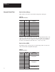
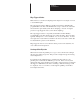
Table 7.E
Binary Data Line Values Using HDAT Strobe
Data Line Value
D0 256
D1 512
D2 1024
D3 2048
D4 4096
D5 8192
D6 16384
D7 Sign Bit: 0 = Positive 1= Negative
D8
D8 and D9 are not used when variable data is strobed in.
in s
D9
Set both l
in
e
s
to 0.
The value is the sum of D0 through D6: D0 + D1 + D2 + D3 + D4 + D5 +
D6 = Value. The seventh wire, D7, is called the sign bit -- numbers can be
positive or negative. The value read during the LDAT strobe is added to the
value read during the HDAT strobe to obtain the value of the variable from
-32,768 to +32,767. Negative numbers are interpreted as two’s compliment
values by the DL20 and should be transmitted that way. Most programmable
controllers use two’s compliment values and no conversion is required.
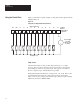
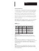
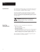
In the BCD numbering system, the data lines are also interpreted differently.
When the HDAT portion of the variable is being strobed in, the lines still
represent two BCD digits; this time the digits are the hundred and thousand
places of the desired variable. Table 7.F defines the new digit weights:
Table 7.F
BCD Data Line Values Using HDAT Strobe
Data Line
Data Line
Value
Comment
D0 100
D1 200
Hundreds Digit (0-9)
D2 400
Hu
n
dred
s
D
igi
t (0-
9
)
D3 800
D4 1000
D5 2000
Thousands Digit (0-9)
D6 4000
Thou
s
a
n
d
s
D
igi
t (0-
9
)
D7 8000
D8
D8 and D9 are not used when
iissin
D9
var
i
able data
is
s
trobed
in
.
Set both lines to 0.
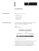
Using the
Parallel Port