
USER MANUAL

A–B
7
Chapter
7–1
The Parallel Port
This chapter describes the parallel port:
• Data formats
• Electrical requirements
• Timing requirements
• AC input converters
• Sampling modes
The DL20 can connect to a programmable controller with parallel outputs.
These outputs can trigger messages and transfer variable data.
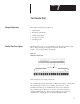
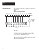
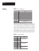
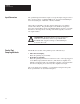
Figure 7.1 shows the parallel port terminals.
Figure 7.1
Parallel Port Connectors
ETS
-
ETS
+
PARALLEL INPUT PORT
MS1 MS0
+5
VDC
OUT GND
11A 11B 12 13 14 15 16 17 18 19
D9 D8 D7 D6 D5 D4 D3 D2 D1 D0
10 11 20 21 22 23
Refer to Chapter 9 for wiring connections.
The parallel input accepts either binary or BCD data formats to transfer data.
The parallel input consists of 12 terminals, divided into two groups.
Terminals in the first group, numbering 10, are known as data lines.
The remaining two are known as strobe lines. The data terminals are
designated D0 through D9. Where data line D0 is known as the least
significant line. The strobe lines are designated MS0 and MS1.
Chapter Objectives
Parallel Port Description