
USER MANUAL

Appendix G
Application Notes
G–7
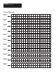
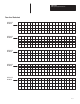
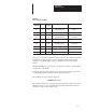
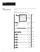
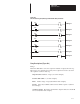
Figure G.2
PLC-2 Ladder Program (Messages with Variable Data) Continued
ZCL
06
032
06
043
Rung 11
07
032
07
043
Rung 12
10
032
00
041
Rung 13
11
032
01
041
Rung 14
12
032
02
041
Rung 15
13
032
03
041
Rung 16
Rung 17
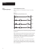
Rung Descriptions (Figure G.2)
Rung 1
Each time TON 031 is done, the sequencer instruction outputs the next step.
These steps were described previously. The sequencer done bit is set when
the sequencer reaches its last step.
SEQ LENGTH: Number of steps (8 for this example).
WORDS PER STEP: 1 (for this example).
FILE: Address range of steps (037-046 for this example).
MASK: Select any available address and set all bits equal to 1 (035 for
this example).
OUTPUT WORD: I/O address at which the output modules for the DL20
are located (010 for this example).