
USER MANUAL

Chapter 9
Installation and Maintenance
9–6
Connecting 1775-GA Peripheral Communications Module
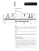
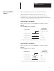
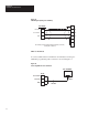
Figure 9.4 shows how to connect an Allen-Bradley Peripheral
Communications Module (Catalog No. 1775-GA).
Figure 9.4
Connecting Allen-Bradley 1775-GA Module
DL20 RS-232 Port
SHIELD (frame ground)
RXD
TXD
SIGNAL GND
RS-232 IN (CLEAR)
RS-232 OUT (RED)
GROUND (BLACK)
1
2
3
7
1775-GA
RS-232C Primary Channel DCE
The wire colors refer to the Allen-Bradley 2706-NC1 and -NC2 cables.
7
6
8
Connecting 1771-DB Basic Module
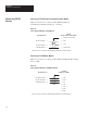
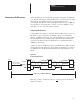
Figure 9.5 shows how to connect an Allen-Bradley BASIC Module (Catalog
No. 1771-DB.
Figure 9.5
Connecting Allen-Bradley 1771-DB Basic Module
TXD
RXD
SG
1
2
3
7
1771-DB
Peripheral Port (DTE)
The wire colors refer to the Allen-Bradley 2706-NC1 and -NC2 cables.
7
6
8
RTS4
CTS5
DSR
6
DTR
20
DL20 RS-232 Port
RS-232 IN (CLEAR)
RS-232 OUT (RED)
GROUND (BLACK)
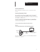
Connecting RS-232
Devices