
USER MANUAL

Chapter 9
Installation and Maintenance
9–3
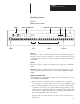
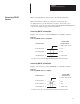
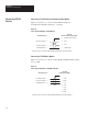
DL20 Wiring Terminals
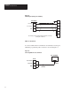
Figure 9.1
DL20 Connection Terminals
KY BD 1 2 3 4 5 6 7 8 9 10 11
RS
422
-
RS
232
OUT
+12
VDC
OUT
ETS
-
ETS
+
E.
GND
RELAY SERIAL COMM PORT PARALLEL INPUT PORT
AC PWR
MS1 MS0
+5
VDC
OUT GND
VAC
HOT NEU
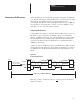
RELAY
KYBD
SERIAL COMM PORT PARALLEL INPUT PORT AC PWR
D9-D0 +5VDC OUT
ETS
11A 11B 12 13 14 15 16 17 18 19
GNDMS0 MS1
D9 D8 D7 D6 D5 D4 D3 D2 D1 D0N.C. COM N.O.
RS
422
+
RS
232
IN
GND
RELAY
(Terminals 1, 2, and 3). Relay is switched whenever specified messages are
displayed. It can be used, for example, to sound a horn and alert an operator
to read the display. The relay contacts are rated for 3 Amperes at 250 VAC
or 30 VDC.
KYBD
This input connector connects optional keyboards (Catalog No. 2706-NK1,
-NK2).
Important: Only the 2706 keyboards may be plugged into this port. All
other programming keyboards must be connected to the SERIAL COMM
PORT.
SERIAL COMM PORT
(Terminals 4 thru 9). The DL20 is capable of two communication protocols
on the SERIAL COMM PORT.
• RS-422 interface on terminals 4 and 5 is typically used to send data to
remote displays or a printer. These devices may be up to 4,000 feet away.
• RS-232 output (terminal 6) can be connected to a printer. RS-232 input
(terminal 7) can be used to program the DL20 or trigger messages. The
GND connection (terminal 8) doubles as an RS-232 common and a shield
ground. The +12 VDC (terminal 9) is for tying RS-232 handshake lines
high. DO NOT USE for any other purpose.
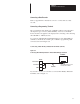
Data recorders, for storing messages on tape, are also connected to the
RS-232 port.